Arduino + AD9850 Frequency Generator
What It Does
The frequency generator does two things - it generates a sine/square signal at 1Hz to 40MHz on one output, and it generates a trimmed fixed crystal controlled frequency on the other. The crystals may be anything, but I have installed crystals for:
- 16MHz
- 18.432MHz
- 20MHz
- 32MHz
These frequencies were chosen as being most useful for my AVR projects. 18.432MHz lets me time things in clock time. 32MHz is the fastest reliable frequency I have used with the newer AVR clocks. I don't imagine I'll run anything near that in a production environment. 20MHz is my preferred frequency for getting things done quickly. 16MHz allows me to select the clock, be an Arduino for a minute or two, then go back to a reasonable frequency.
The outputs are selected using one of the $2 16-key membrane keypads I thought I would never find a use for. An
I2C LCD shows you what is going on. The enclosure is a Twin Industries B30-8000 with PCB ($19.00).
The blue I
The AD9850
The AD9850 is a chip that uses Direct Digital Synthesis (DDS) to generate sinusoidal waveforms from 0.0291Hz to 62.5MHz using a 32-bit divisor of a 125MHz clock. It manifests itself in the form of cheap (~$10) imported boards with a circuit right from the datasheet. I have seen several versions, differing in the PCB layout or in the size of the oscillator. Some have pads for both a small SMD oscillator and a 1/2 size DIP oscillator, and boards are available with either. Mine has the small oscillator. At 32MHz output the Tek scope's frequency counter shows 32.0000MHz, so the thing is accurate.
Arduino
The Arduino is the Arduino Pro Mini, and all lines are used, except A6 and A7 if you have a board with A6 and A7. The Arduino controls the AD9850 board, reads the 16-key keypad, drives the LCD display, and directs the proper crystal oscillator to output its clock. I'm actually using a $3.50 clone, but they are pretty much all the same.
The User Interface
A 16 character x 2 row LCD display shows the current frequency and the crystal oscillator selected. The keypad number buttons are just numbers, but the other buttons are assigned these functions:
- "A" is the edit generator frequency button
- "B" is the select fixed crystal oscillator button
- "C" restores the configuration stored in EEPROM
- "D" stores the current configuration in EEPROM
- "#" is the "ENTER", and "YES" button
- "*" is the "Backspace" and "NO" button
To set the frequency, you push the "A" button, then enter the frequency in Hertz. "*" acts as a backspace. "#" updates the AD9850 with the new value. Stopping for more than 5 seconds during editing exits edit mode, leaving the configuration as it was. The frequency is entered directly - 1 is 1Hz, and 32000000 is 32MHz.
To select a crystal, hit "B" to enter edit mode, then keep hitting "B" until you get to the desired crystal. Then press "#" to change to that crystal. Hit "*" or just leave it alone for five seconds to revert.
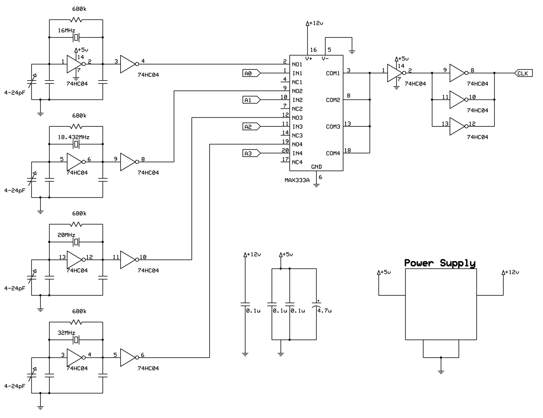
The schematic (click for a larger version) shows the crystal oscillator circuit. It works by switching crystal oscillators using a MAX333 analog switch. The output is paralleled for higher drive into the coax cable.
I am working on a replacement that uses the still somewhat available, 74F138 instead of the MAX333. The 74F138 is a single TTL chip called a multiplexer, and it can replace the MAX333, leaving the signals in the digital domain. It also costs significantly less. The 12V power supply requirement goes away with the digital solution, too.
The input voltage should be between 12V and 24V. My "12V" adapter is 14V, and that works well. The analog switch needs the voltage to switch properly. The circuit won't work at all below 10V. One problem that comes up is the current draw of the DDS board and the high incoming voltage. It adds up to a linear regulator that glows red. The solution is a cheap LM2596 switching regulator module.
A word of caution - the two sine wave outputs of the DDS are around 1Vpp, but the square wave outputs and crystal circuit are a full 5Vpp. Don't fry something. The sinewave is adequate for supplying an external clock to an AVR, even one set for an external crystal.
Power consumption is 75.5mA @ 14.3V or 1W.
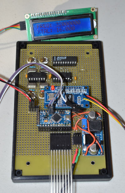
The picture shows the completed board. The crystal oscillators are at the top, then the AD9850 DDS, the Arduino, and the power supply. The wires on the left are for the I2C LCD and the wires on the right for a pot that controls the symetry of the square wave output. The keypad ribbon goes off the bottom of the picture.
The odd board locations are so I could run bare wires straight across from pin to pin without worying about shorts. The keypad signals on pins 2 through 9 run pin-for-pin to the connector, and the AD9850 signals on pins 10 through 13 are pin-for-pin to the AD9850 board. Socket everything to be safe. The DDS board runs very hot at higher frequencies, and it could conceivably fry itself.
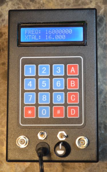
The finished frequency generator. The left-hand BNC connector is for the crystal output, and the righthand BNC is for the variable output. One switch selects sine or square, one is the power, and the knob sets the square wave symetry. The power jack is for 12VDC, center positive.