Assembly
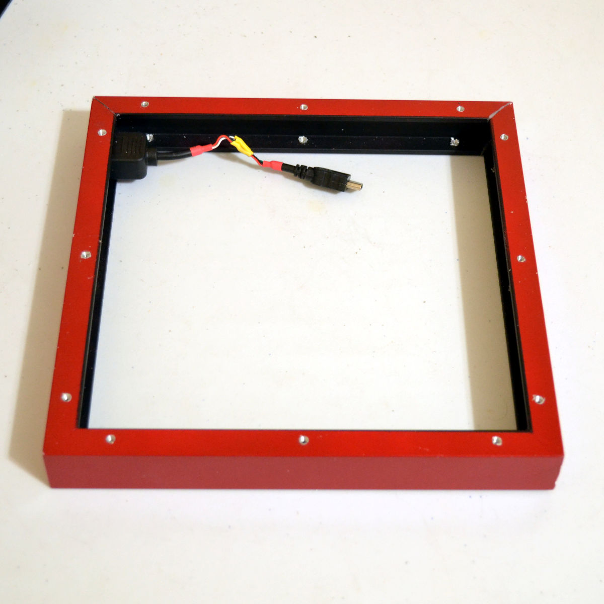
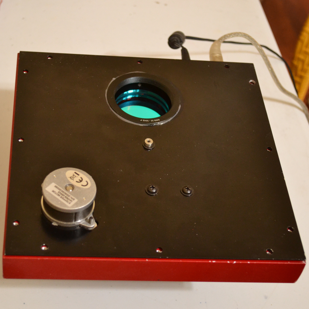
The electrical cables were mounted on the side frame, to be routed to the electronics. The cables need to be close to the front panel to keep from interfering with the wheel.
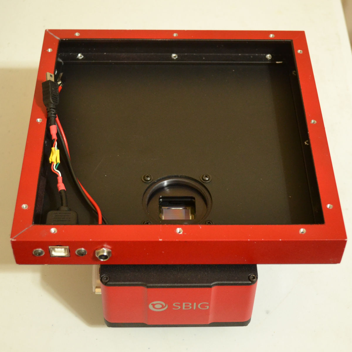
The rear panel is mounted on the side frame, and then the camera is mounted on the rear panel. The camera body covers one of the screws, so the camera couldn't be mounted first.
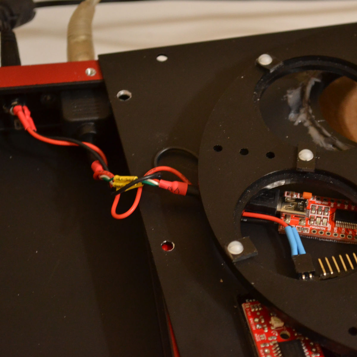
The cables are connected to the front panel USB to serial converter and the controller board. I put a little twist in them so that when the front panel is flipped to its place, the cable will want to lie against the front panel.
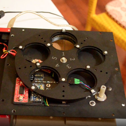
(video) Time to test before adding the filters. I used the Arduino IDE's Serial Monitor to send the commands 1,2,3,4 and 0 to the controller and it executed them as fast as it could. You can see it center each filter in turn.
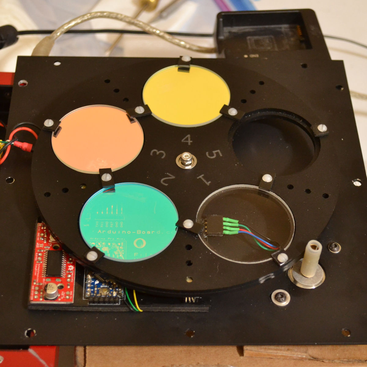
The filters are oil and dust magnets and aren't easily cleaned, so I picked up some white cotton gloves like archivists use. The filters were added one at a time to prevent warping the wheel.
The front panel has to be jockeyed a little to get it exactly in place, due to the cables. I screwed in the 12 screws and gave it one more test to see that it wasn't hanging up on the cables.
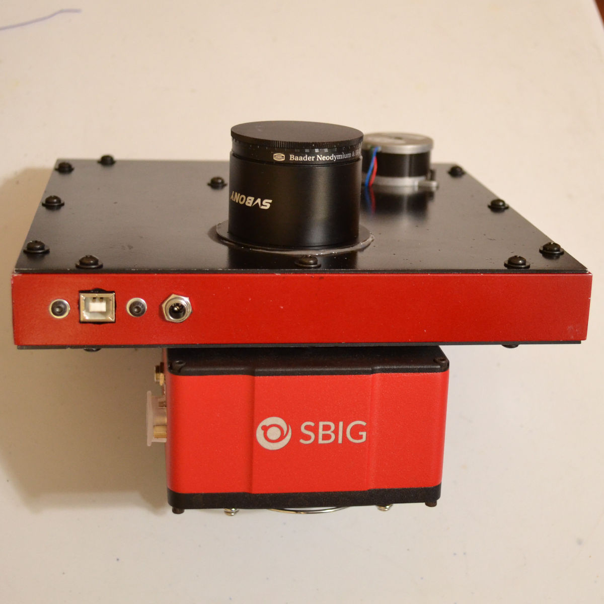
With the addition of the nosepiece and IR cut/skyglow filter - done.
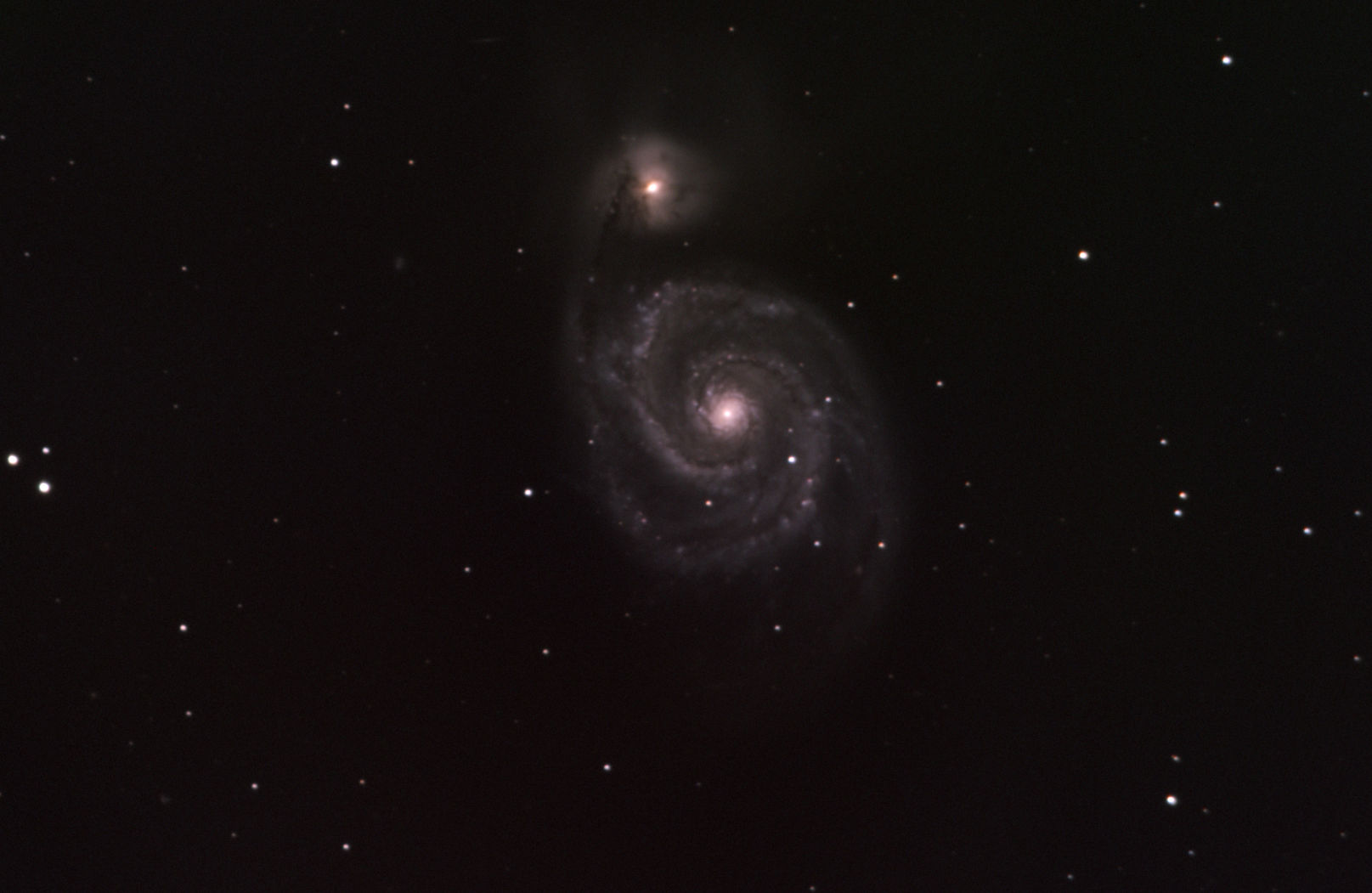
An LRGB "first light" image to test it out. 72 minutes luminance, and 30 minutes each R, G and B.