Computerized Telescope Power Distribution V2
Skip to the end: Power Box 5
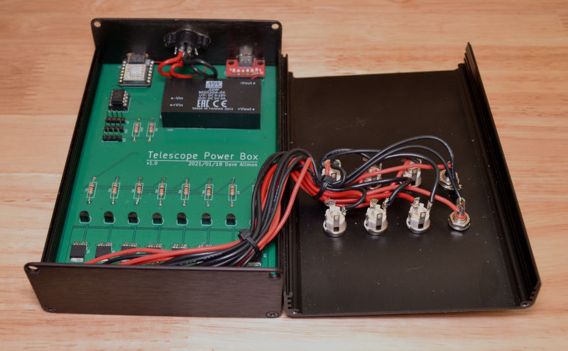
I built a 6-port telescope power supply box last year, and it has worked out pretty well, but I found myself needing switches on two channels for the scope and camera. I decided to make them software controllable, and made all six channels switchable. I added two dew heater outputs in case I need them sometime. The only physical restriction on the project was that it had to fit in the same size box, since it needs to mount in the same place on the scope. The box has card slots, so I made a 4" x 6" PCB to fit.
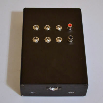
Switched Outputs
Each of the six outputs is capable of providing up to 8A but the total can't exceed 11.5A (my supply max). Each may be set to auto start on power up or not. The outputs are all on the top of the unit, in two rows of three. The jacks are high quality Switchcraft 5.5mm x 2.5mm and are compatible with locking plugs. I didn't have enough I/O to implement current sensing, although the switches I used have a current sense output that will alert on faults, or give an analog signal proportional to current.
Heater Controllers
The heater controller is a proportional temperature controller which attempts to regulate the temperature of a probe near the glass to just above the dew point. The dew point is calculated from the ambient temperature and relative humidity. The number of degrees above dew point is configurable. When a temperature error is seen, the controller calculates the PWM and adds a configurable minimum value to it. Attempting to set the PWM value when in auto mode will result in an error response from the controller. In manual mode the PWM is set directly, and it runs open-loop, without temperature regulation. The heaters cannot be put into auto mode if the temperature probes are not connected. The PWM frequency is 15Hz.
The heaters are not included in the total current requirements below. That's because I live in a place that doesn't often have dew. If I needed the dew heaters I would also need a larger DC power supply, and would have to switch from a power brick to an open or closed frame power supply. That would require another box, and I'm keen on avoiding another box.
Electronics

Key Parts List:
| Item | Description | Price |
|---|---|---|
| MDS20A05 | Meanwell 5V 4A DC-DC converter | 40.06 |
| KPJXPM4SS | Kycon locking mini-din socket | 3.21 |
| 712AH | Switchcraft 2.5mm x 5.5mm DC barrel socket (x6) | 20.22 |
| 4006H-6B | Context split-body aluminum enclosure 6.0" L x 4.13 W x 1.5622" H | 23.95 |
| - | PCB | 8.50 (*) |
| 10kΩ 1/4W | Resistor (x10) | 1.00 |
| BTS5012SDA | Infineon BTS5012SDA high side switch (x8) | 18.40 |
| 2N3904 | NPN small signal transistor 30V TO92 (x8) | 1.45 |
| 24LC64 | Serial EEPROM 8k x 8 | 0.48 |
| - | Seeeduino XIAO Microcontroller board | 4.90 |
| BOB-15100 | Sparkfun USB-C breakout | 4.50 |
| Total | $126.67 (**) |
* For one PCB when I bought 10 from the fabricator.
** I have the power brick from version 1.
The smarts for this are on the Seeeduino XIAO board, a 32-bit ARM M0 Arduino compatible the size of a postage stamp. As soon as power is applied, the Raspberry Pi gets its 5V, and the same 5V powers up the XIAO. The XIAO then reads settings from the EEPROM, turns on the auto-start ports, and waits for commands. It also auto-starts the heaters, if they were in auto mode when last powered down.
The switching is done by BTS5012SDA MOSFET high side switches. They are the type of thing used for automotive turn signals, brake lights, etc. Maximum continuous current rating is 8A typical. A 2N3904 NPN transistor isolates the 3.3V XIAO I/O port signal from the the 12V enable pin on the MOSFET switches. The high-side switches don't warm up noticeably with 5A going through them. I was surprised.
The 5V @ 4A power supply is a medical grade, isolated, regulated 20W DC-DC converter from Meanwell. It has a 1" x 2" footprint. At 86% efficiency it warms very little when running the Pi. It was a little expensive, but it works well with the Raspberry Pi 4B. It can be particular when it comes to USB-C cables. Long and/or cheap cables don't work.
Power Input and Output
The board can handle 18A total on the switched and heater ports. It is 2oz. copper plated, rather than the typical 1oz. The input connector is good for up to 15A (7.5A per pin, two 12v and two ground).
The biggest current hog I have is the camera, which uses a bit over 5A when running the cooler at 100%. I typically run it below 80%, so 4A. The telescope is second at 3.5A while slewing at max speed in both axes (I run it at half speed). Other outputs feed the focuser, filter wheel, flat fielder and the USB3 hub. The hub provides power to the ASI290MM Mini guide camera, filter wheel serial converter, the flat fielder MCU, and the focuser MCU. I have the six channels assigned like this:
- USB hub (0.5A)
- Telescope (3.5A)
- Camera (5A)
- Focuser (0.6A)
- Filter wheel (0.8A)
- Flat panel (0.5A)
It isn't reasonable to run more than a couple of things together. Many combinations don't make any sense. You wouldn't focus or flat field while slewing, or change filters while focusing, for instance. So although the total is approximately 12.4A, the real world peak current might be more like 7.25A - slewing at half speed while the camera is cooling at 80%, with the Raspberry Pi running. You can see how difficult it is to determine how much current the power supply should deliver. It's so variable.
Computer Interface
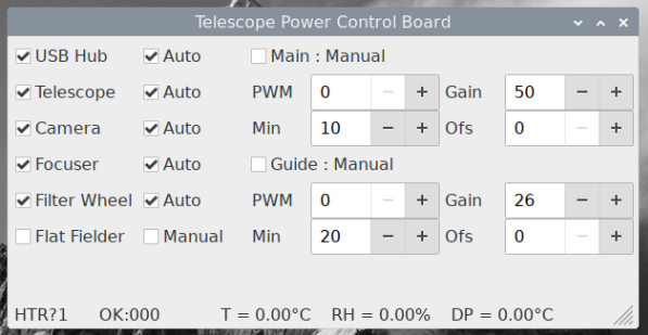
The Xiao code has an interface, and during initial testing I used the Arduino serial monitor to talk to it. Later I put together a python app with wxPython which is shown below. The app was written on an Ubuntu system, and then copied to the Raspberry Pi. Installation on the Raspberry Pi was complicated by the need for wxPython to be compiled, which took an hour or so on the 4GB Raspberry Pi 4B.
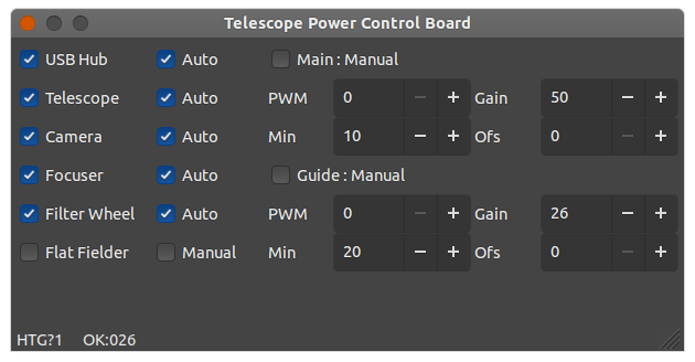
The names and order of the channels are in a config file, so editing that file is all that is required to change things around. The software can be configured with any two ports. They are not serial ports as such, but show up as 'ttyACM0' or 'ttyACM1'. If it can't get the version from the first one, it tries the second. If that fails, the program ends.
Thoughts
If I were to do this again, I might use a Teensy 3.2 board as the controller. It has 34 I/O pins, 21 of which may be used as analog inputs. That would allow me to monitor the input voltage and the current through each of the switches.
So far, no troubles at all. I've replaced the old plugs on the equipment with new locking plugs. In the process I discovered that I have been using a 2.5mm plug on the scope, which has a 2.1mm jack. That explains some odd behavior.
As long as power is applied to the power box, the Pi is running. This thing could be completely automated if I had the means to power-cycle the power box (and therefore the Pi) if the Pi hangs for any reason. A task that pings an ESP32, which has a relay to control the AC power, would be a good watchdog. No ping in 10 minutes = power cycle the box. Anyway, that's for another time.