Computerized Telescope Power Distribution Box V4
In this, the 4th installment in the power control box series, I've put together a solution that is closer to what I imagined in the first place - 8 each 12V power ports, individually controllable, and individually monitored for current usage. The 2 heater ports, which have never been used, are gone and the ports added to the 6 original switched ports. Skip ahead to the Power Box 5 project to see how this all ends.
There were lessons learned in the first three boxes, especially with v3. I've beefed up the analog circuitry and tightened the maximum voltage from 3.3V down to 2.0V. There was a 1kΩ resistor in series with the analog input, with a 3.3V zener. I've changed that to a 4.7kΩ resistor, a 2.0V zener, and added another 4.7kΩ resistor and a 0.01μF film capacitor as a noise filter. It turns out that the high-side switches can output from 5V to 12V on the sense line when overloaded. One of my barrel connectors developed a dead short to ground, and current flowed. The 5% tolerance on the zeners meant the voltage could rise above 3.3V on the analog input, and the Teensy fried. Funny thing: The power circuitry wasn't damaged, but one can't buy a Teensy 3.2 anywhere now, and the builder won't have any more for 9 months.
So a little redesign was done. I traded the Teensy 3.2 in on a Teensy LC, which is more than adequate, having (at least) the required 8 digital pins and 9 analog inputs. I have a Raspberry Pi Pico, and the Seeed Studio Xiao, both of which are cheap and available, but neither of which can handle the required digital and analog. The Xiao, used in the Power Box v2, just didn't have enough total pins. The Raspberry Pi Pico, with many digital pins, has only 3 analog pins!
I also separated the Teensy power from the 5V power supply. I changed it so that the power goes from the 5V supply to the Raspberry Pi, and the Raspberry Pi powers the Teensy through the USB cable. Why? Because the Teensy would power up the Pi through the USB cable, but not enough to let it boot, so it would hang on boot a lot of times. It hasn't happened once since I split the two paths.
Schematic Diagram

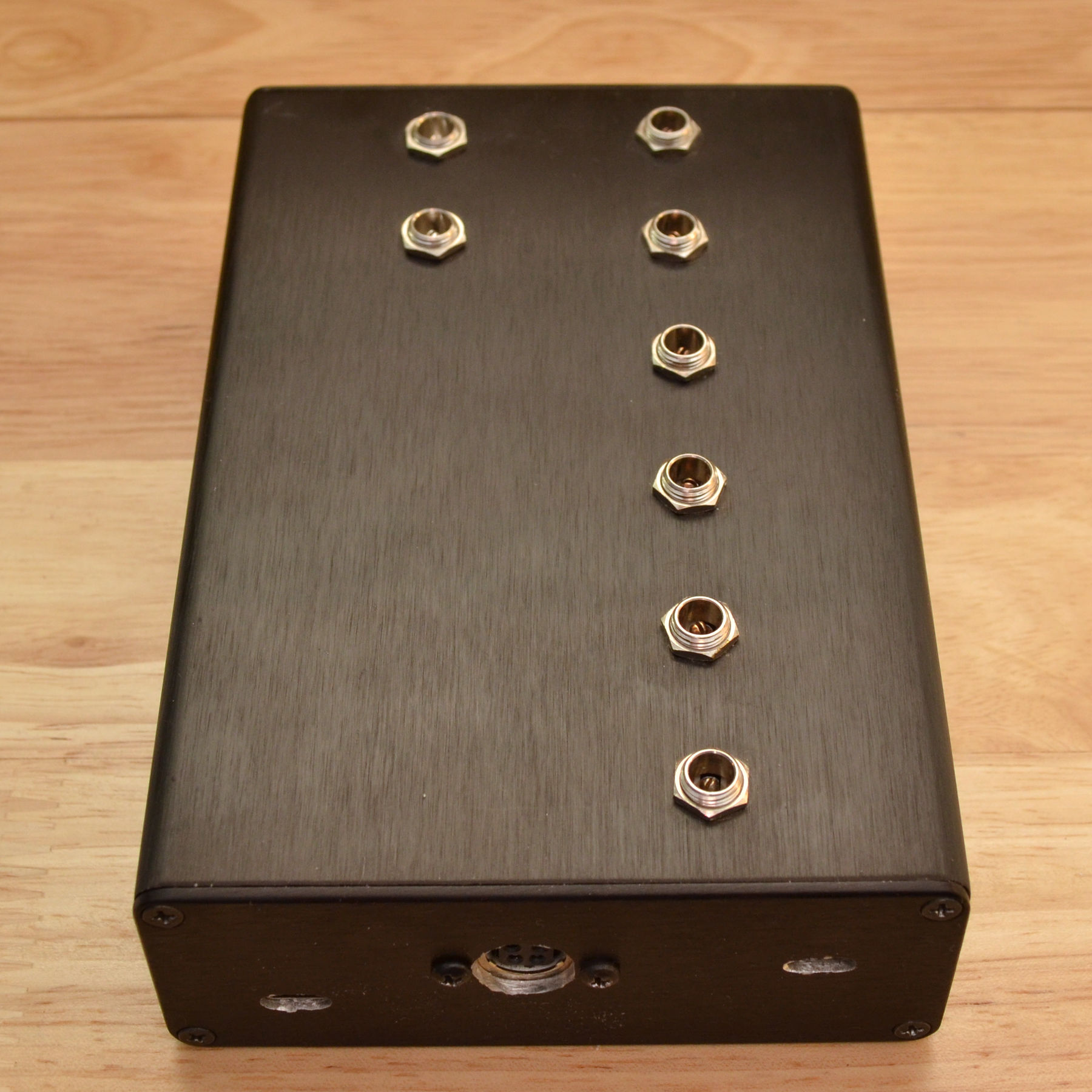
Although there is a little more circuitry, the board is the same size as v3. There is an external 32k x 8 EEPROM again, since the Teensy LC has no real EEPROM. The schematic shows a barrel jack for power input, but I went with the same 4-pin locking DIN connector, which matches the 12V power supply, and is good for over 14A.
The circuit is not complicated - it is just the same circuit 8 times, with 2 lines going back to the Teensy from each circuit.
PC Board
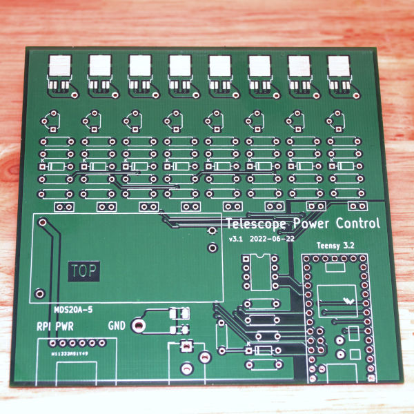
I got the PC boards from PCBWay.com. This is sort of an anniversary. I was looking at my history, and PCBWay has made PC boards for me 30 times, and not one bad board. And the finish and solderability are always excellent. I enjoy the whole process of designing a board, uploading the Gerbers, and in about a week, getting boards back from them, halfway around the world. PC boards make my designs real, and they're important to me. Like most PCB houses PCBWay boards default to 1oz copper, and a maximum size for the basic board. Unlike some other PCB houses, their quality of workmanship isn't forsaken for speed and cost. They consistently provide me with high quality boards. Their basic size is up to 100mm x 100mm, and they provide 10 copies for $5.00 plus shipping. Sweet deal for quality boards. Over the 100mm x 100mm size you pay by board area. Still a bargain. Most of my designs fit in the 100mm x 100mm footprint. For these power boxes I've been using 2oz copper, which costs a little more, but helps carry the current. Also, because of the 4" width of the card slots in my box, these boards have to be 101.6mm wide.
Parts
| Item | Description | Needed/Bought | Price |
|---|---|---|---|
| MDS20-05 | MeanWell 5V 4A DC-DC converter | 1/0 | 41.11 |
| 712AH | Switchcraft 2.5mm x 5.5mm DC barrel socket | 8/0 | 26.96 |
| 4006H-6B | Context split-body aluminum enclosure 6.0" L x 4.13 W x 1.5622" H | 1/0 | 23.95 |
| - | PCB | 1/1 | 7.96 |
| 4.7Ω 1/4W 1% | Resistor | 26/100 | 3.00 |
| 1kΩ 1/4W 1% | Resistor | 8/10 | 0.76 |
| 1.5kΩ 1/4W 1% | Resistor | 1/10 | 0.76 |
| 15kΩ 1/4W 1% | Resistor | 1/10 | 0.76 |
| BTS443P | Infineon high side switch | 8/10 | 28.80 |
| 2N3904 | NPN small signal transistor 30V TO92 | 8/0 | 3.15 |
| -- | 2.0V zener | 10/10 | 8.71 |
| Teensy LC | Teensy LC Microcontroller board | 1/1 | 13.00 |
| -- | Sparkfun clone USB-C breakout | 1/0 | 4.50 |
| Total | $163.42 |
Most of the parts are leftovers from V3, but a few parts had to be purchased. The little DC-DC converter has seen use in 3 power boxes now. The input current at 3A output on the DC-DC converter is 1.45A, which is not part of the measured amp hours.
Arduino Power Box Source: pwrctl_teensy_4.zip
Python Control App source: pwrbox4.zip
I had to modify 'boards.txt' as in this post, in order to get printf to work with floats. It increased the flash memory usage from 53% to 83%, but without it there's no current monitoring.
Current Sensing
The switches push a current out of the sense pin proportional to the current in the main output. It is approximately 1/8200 of the output current, so 1A gives 122µA at the sense output. It produces 122mV across the 1k sense resistor. 10A produces 1.22V. The ADC reference is set to 1.402V, so 4095 ADU = 11.53A. That 1/8200 number is nominal. At different temperatures and output currents it has a different ratio. The data sheet goes into a some detail as to what the ratios might be, in a large range, but for any given part, the ratio is defined by a possibly unique, more-or-less straight line. Infineon suggests that every part be individually calibrated, and that's what I've done.
The high-side switches can be hard to find. I was after the 8 amp BTS6133, but failing to find any, I ordered the 7 amp BTS443P. They have an ISO rating of 25A, but a nominal rating of 7A. I guess I don't know what the ISO rating means. Something I noticed during testing was the fact that the error in the sense voltage on the BTS443P is lower than that of the other switches I've used. So much so that they probably don't require calibration at all.
The Teensy 3.2 had a 1.2V internal reference, while the LC's internal reference is the 3.3V power supply. I changed the LC's ADC reference from internal to external, and used a 2.0V zener. I didn't change the reference until after I ordered the PC boards, so I had to make a simple kludge on the board. It would work without it, but the range wouldn't be as good. The reference voltage is 1.402V. I don't really care, as long as it is stable, and it seems to be. The 3.3V power supply is just too noisy to use as an analog reference.
Voltage
The input voltage is measured right where the supply leads connect to the board. Voltage doesn't really matter much - it's the amp hours I'm interested in, but the voltage reading under load can indicate a low battery, or problems with the power supply or wiring.
What is the result?
The loads on the power box vary. The telescope uses more power when slewing, the camera more when cooling down, the filter wheel when changing filters. The USB hub supplies power to the EAF focus motor, guide camera, GPS receiver, three USB-Serial converters, and one Arduino Nano. I considered the typical current to be when the scope is tracking, guiding, and the camera has cooled, but is still maintaining the temperature.
| Device | Current (typ.) | Current (max) |
|---|---|---|
| USB Hub | 0.229 | 0.229 |
| Telescope | 0.246 (tracking) | 0.86 (slewing x4°/sec) |
| Camera | 1.228 (80%) | 1.644 (100%) |
| Focuser | 0 | 0.348 |
| Filterwheel | 0 | 0.194 |
| Flat Fielder | 0 | 0.38 |
| Available | 0 | 0 |
| Available | 0 | 0 |
I normally don't turn the flat fielder power on until after I put it on the scope and hook it up, because when it's powered up it puts out over 100Vac, and I don't want a shock.
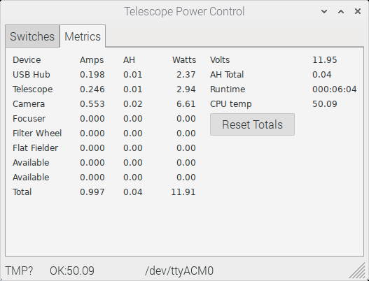
The camera, in addition to the 1/2 amp on the 12V line draws some power from the USB. The 1/4 amp used by the telescope is when the scope is tracking, and the handset lights are still on.
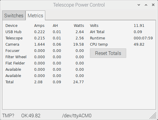
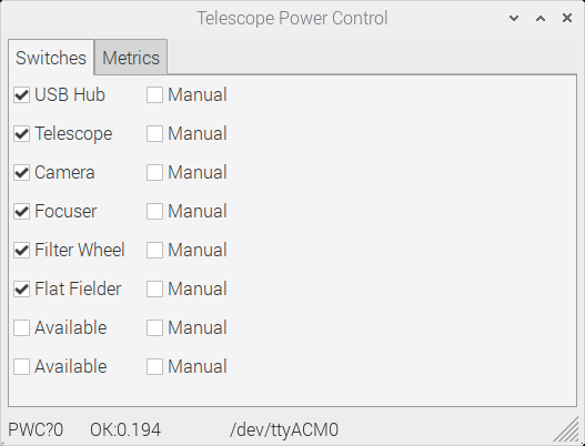
The "Reset Totals" button clears the accumulated values of time and amp hours. It does not reset the power box.
I see one more power box in my future. It will do everything this one does, and also monitor the current used by the Raspberry Pi and will be able to power-cycle the Raspberry Pi remotely. Then my quest for telescope automation will be complete. Maybe.
Back to Telescope Power Distribution