Computerized Telescope AC Power Control Box
I came across a need to independently switch two AC power outlets - one for the mount, and one for everything else. It needed to be completely separate from the Raspberry Pi running Stellarmate, since in one state the Raspberry Pi would be powered off. I already had Wi-Fi in the dome, so it was an easy decision to use Wi-Fi for the AC switch. It wouldn't take too much processing power, but it would require a web page to control the relays and show their status.
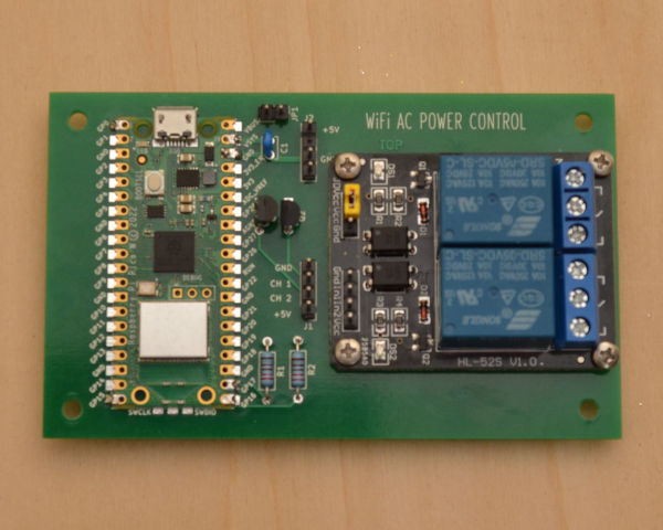
The Raspberry Pi Pico W seemed like a good fit. Wi-Fi, 2MB Flash, 264kB RAM, small size, and $6.00 each. It's surface-mountable by way of castellated pads. A 2-channel 5V relay board switches the power to the dual tamper resistant outlet. I picked up the relay board on Amazon.
NOTE: All electrical work comes with inherent risks, so make sure to carefully follow basic wring practices. If you need to learn relay switching, practice with a 12VDC or 24VAC project, rather than 120VAC. If you must switch 120VAC, consider purchasing a pre-built Wi-Fi switch. They are relatively inexpensive, but the same attention to safety is required for them. Amazon sells Wi-Fi switched outlet/plugs four for $25.00 or so, and they include timers and light sensors. Carefully read the following to determine if your skills and understanding are sufficient to do the job. If in doubt, do not attempt this project.
Schematic Diagram

The circuit consists of a Raspberry Pi Pico W, with two pins driving two NPN transistors, which in turn drive a dual relay board. The Pico W max output current is configurable, but defaults to 4mA. The relay board is spec'd at 25mA input current, so the transistors are required. The transistors are 2N3904 GP/Small Signal devices capable of sourcing 100mA. A 5Vdc wall-wart supplies the power to the Pico W and the relay board. When the controller decides to turn on an outlet, it raises a 3.3V output, which turns on the transistor. The transistor conducts, pulling the opto-isolator input on the relay board down and energizing the relay. Lowering the output to 0V turns off the transistor, and relaxes the relay.
The relay board is not shown. There is a place for it on the PC board, but it connects with 4 jumper wires, so it could be anywhere. I didn't attempt to run traces to it, because that would force me to use a relay board that was pin- and size-compatible with the one I had when I designed the circuit. This circuit could be expanded to four or even more relays, as long as they have 5V coils and don't use more current than the wall wart can provide. The relay board has relays rated 10A@125VAC. My application needs about 0.5A through each relay. Choose your parts carefully. If you are going to do something like this, make sure the wires can easily handle the current and voltage, the relays can switch the load, and the transistors can handle the relay board inputs. Always use opto-isolator relay boards when switching high voltage. Use only 5V relay boards with this circuit! The 5V powers the relay board and the Pico W, which has a maximum input voltage specification of 5.25Vdc.
PC Board
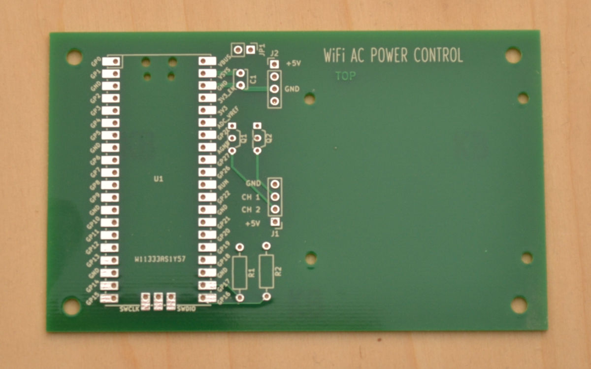
The PC boards were made by PCBWay. There is a PCBWay plugin for KiCad that allows you to push a button and order from them. I do that, wait 1 to 3 days, and my boards are finished. You can monitor the progress through the manufacturing process, station by station. The price is right and the quality is great. They make it really easy to get high quality PC boards, and I use them for all of my projects. I recommend PCBWay to anyone looking for fast, quality prototype PC boards. I recommend DHL shipping, too, since they can deliver the boards to the US in 2 - 4 business days. A more rapid turnaround than most local shops, and lower cost.
Firmware
import network
import socket
from time import sleep
from machine import reset, Pin


ssid = '********'
password = '********'
mount_state = 'Currently Off'
scope_state = 'Currently Off'
mount = Pin(17, Pin.OUT)
scope = Pin(16, Pin.OUT)


template = """
<html>
<head>
    <title>Power Control v1.0</title>
    <style>
        body, html {font-size: 20px; font-family: "DejaVu Sans",sans-serif;}
        .hdr {width: 100%; height: 50px; background-color: #7f7f7f; color: white; font-size: 32px; text-align: center; line-height: 50px;}
        .group {width: 270px; height: 375px; border: 1px solid black; border-radius: 7px;margin: 4px;}
        .channel {width: 250px; height: 125px;margin: 20px 5px 5px 5px; border-radius: 5px;border: 1px solid black; padding: 4px;}
        .indicator {width: 250px; height: 24px; border-radius: 4px; color: white;text-align: center;}
        .indicator.on {background-color: green;}
        .indicator.off {background-color: red;}
        .btn {width: 250px; height: 32px; border-radius: 4px; border: 1px solid #7f7f7f; text-align: center; margin-top: 8px; background-color: #3f3f3f; color: white;}
    </style>
</head>
<body>
    <div class="group">
        <div class="hdr">
            <span>Power Control</span>
        </div>
        <div class="channel mount">
            <div class="indicator --mount-class--">--mount-state--</div>
            <form action="./mount-on">
                <input type="submit" id="mount-on" class="btn" value="Mount On">
            </form>
            <form action="./mount-off">
                <input type="submit" id="mount-off" class="btn" value="Mount Off">
            </form>
        </div>
        <div class="channel mount">
            <div class="indicator --scope-class--">--scope-state--</div>
            <form action="./scope-on">
                <input type="submit" id="scope-on" class="btn" value="Scope On">
            </form>
            <form action="./scope-off">
                <input type="submit" id="scope-off" class="btn" value="Scope Off">
            </form>
        </div>
    </div>
</body>
</html>
"""

def webpage(mount_state, scope_state):
    #Template HTML
    if mount_state == 'Currently On':
        mount_class = 'on'
    else:
        mount_class = 'off'

    if scope_state == 'Currently On':
        scope_class = 'on'
    else:
        scope_class = 'off'

    templ = template.replace('--mount-state--', mount_state).replace('--scope-state--', scope_state).replace('--mount-class--', mount_class).replace('--scope-class--', scope_class)
    return str(templ)

def connect():
    #Connect to WLAN
    wlan = network.WLAN(network.STA_IF)
    wlan.active(True)
    wlan.connect(ssid, password)
    while wlan.isconnected() == False:
        print('Waiting for connection...')
        sleep(1)
    ip = wlan.ifconfig()[0]
    print(f'Connected on {ip}')
    return ip

def open_socket(ip):
    # Open a socket
    address = (ip, 80)
    connection = socket.socket()
    connection.bind(address)
    connection.listen(1)
    return connection

def serve(connection):
    #Start a web server
    global mount_state, scope_state, mount, scope
    while True:
        client = connection.accept()[0]
        request = client.recv(1024)
        request = str(request)
        try:
            request = request.split()[1]
            if request == '/mount-on?':
                mount_state = 'Currently On'
                mount.value(1)
            elif request =='/mount-off?':
                mount_state = 'Currently Off'
                mount.value(0)
            elif request == '/scope-on?':
                scope_state = 'Currently On'
                scope.value(1)
            elif request == '/scope-off?':
                scope_state = 'Currently Off'
                scope.value(0)
            else:
                print(request)
                pass
        except IndexError:
            pass
        html = webpage(mount_state, scope_state)
        client.send(html)
        client.close()

# Execute from here.
try:
    ip = connect()
    connection = open_socket(ip)
    serve(connection)
except KeyboardInterrupt:
    machine.reset()
First, you need to install micropython on the Pico W.
- Download the firmware from the link just below.
- Unplug the USB cable from the Pico.
- Press and hold the BOOTSEL button while plugging in the USB cable.
- Release the button. The Pico should show up as a new drive on your computer.
- Copy the '.uf2' file you downloaded above to the new drive.
- It will take a while, but it will eventually copy, and then disappear from the new drive.
You should now have the newest version of micropython on the Pico W.
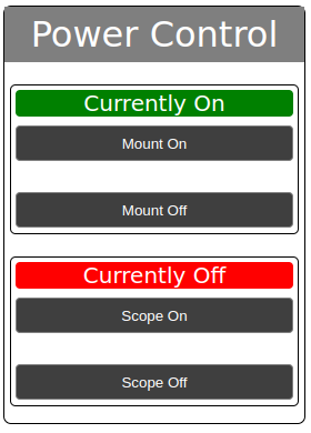
The program consists of two parts. The first is the data for the page and the code that manipulates it based on the state of the two relays. The second is the code that serves the page, determines the state of the two relays, and sets the relays to that state.
If you have a problem, like ImportError: no module named 'network', try downloading and installing
the latest MicroPython for the Pico W again.
I use Thonny or PyCharm to work with the Pico and Pico W. Don't let Thonny upgrade the MicroPython! It gets it from the
main micropython gihub repo and that version does not include the network module. The firmware linked above is made just for the Pico W board.
The Box
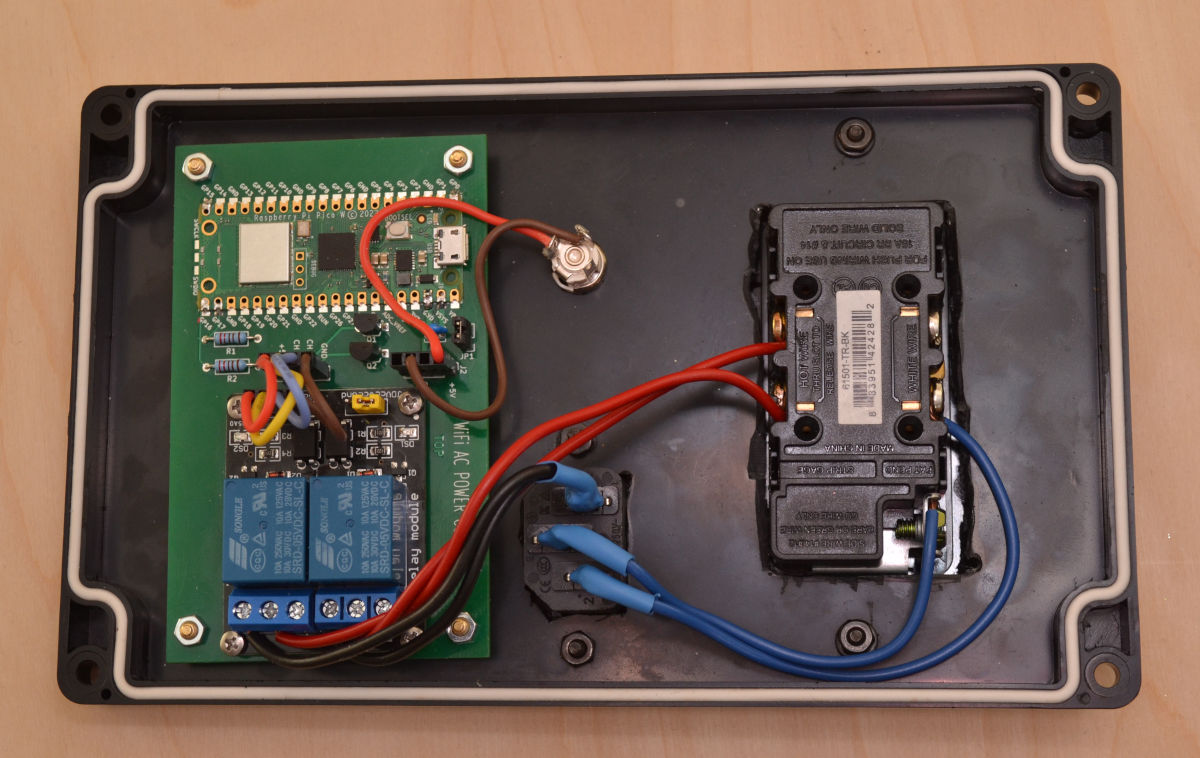
The box I chose is a water-resistant plastic box that is 7.87" x 4.72" x 2.95". The 4.72" dimension is important. A dual outlet will fit nicely in that space, as will the power control board. I decided to mount everything to the lid of the box to avoid holes in the bottom. The outlet has the hot (LINE) wire shorting tab broken off, so the outlets can be powered from two different sources. The NEUTRAL shorting tab is left intact.
The LINE 'L' IEC wire connects to the N.O. contact on each relay, and the COMMON contact on each relay connects to the corresponding LINE (BRASS) terminal on the outlet. The NEUTRAL 'N' IEC wire connects to the NEUTRAL (SILVER) side of the outlet. The GROUND wire goes from the IEC 'E' input to the ground (GREEN) screw on the outlet. Don't get them mixed up. Check your local electrical code if you need to.
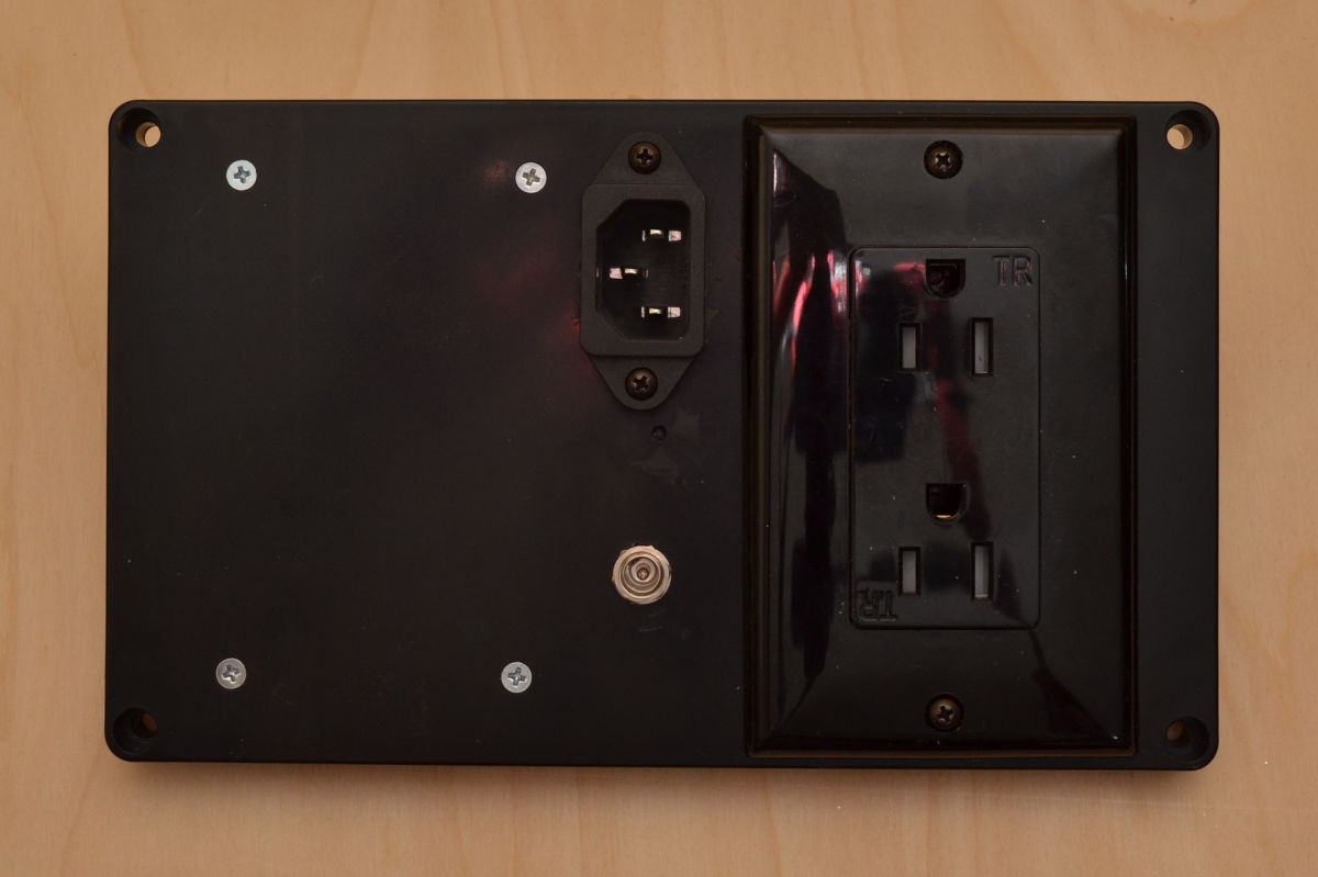
The front panel of the box showing the AC in and AC out, along with the 5V input. The box runs a 15Vdc, 8A power supply, feeding a Power Box 5 from one outlet, and a 15V 5A power supply, which powers the Losmandy mount from the other.
This project was sponsored in part by PCBWay.com.