DIY Servo SubWoofer (Velocity Feedback)
A 10Hz Subwoofer
One side effect of motional feedback of any kind is it can push the frequency down below the driver and cabinet resonance. With velocity feedback this 10" subwoofer has flat-ish near-field response from 10Hz to 150Hz. The effect of having such a small a cone is that you can't produce a lot of acoustical power down there. Fortunately this sub is just for music, and not for special effects. I would want a 15" sub for home theater. Also, keep in mind that this feedback will not work on a ported speaker box.
Box and SD270A-88 Driver Response
Bode plot of the driver in the enclosure, without velocity feedback. The woofer is in an enclosure with an internal volume of 73 liters, giving QTC = 0.669, f3 = 43Hz. The free-air resonance of the Dayton Audio SD270A-88 is 26.2Hz.
A dual voice coil driver has two nearly identical windings on the same coil form and moving in the same magnetic field. One coil can be driven and the other used to provide velocity feedback, if the feedback signal is compensated [1]. My plots do not look exactly like theirs, because their velocity is coil voltage w.r.t. laser-measured velocity, where mine is coil voltage with a zero reference.
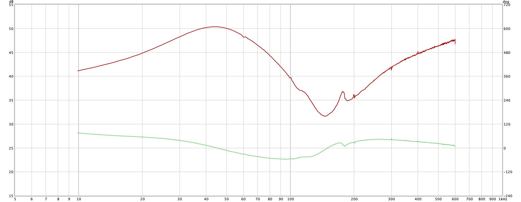
With any dual voice coil low frequency driver, the signal is not really a perfect match to the velocity of the cone. There is mutual inductance between the two coils that causes a 180° phase shift and a dip in the amplitude response. The frequency of this anomaly is higher than my subwoofer's crossover point, but its effect is still within the crossover region. Below f0 there is a broad peak which needs to be removed as well.
The disturbance in response can be counteracted by a 2nd order notch filter, with f0 = 146Hz. That puts the feedback back in line with the actual cone velocity, at least enough that the crossover can go above the current 70Hz.
Test Fixture
I built a fixture to hold a 50W stereo amplifier board and transformer, ±15V supply and transformer, a large breadboard, a USB DAC and UMC22 input device. The DAC is used by REW to generate the sweeps. The UMC22 is used to read the feedback signal into REW, which analyzes the data and generates plots. The ±15V supply is for the breadboard, which has the experimental feedback compensation circuit on it. For frequency response curves I used a MiniDSP UMIK-1.
Velocity Feedback Circuit
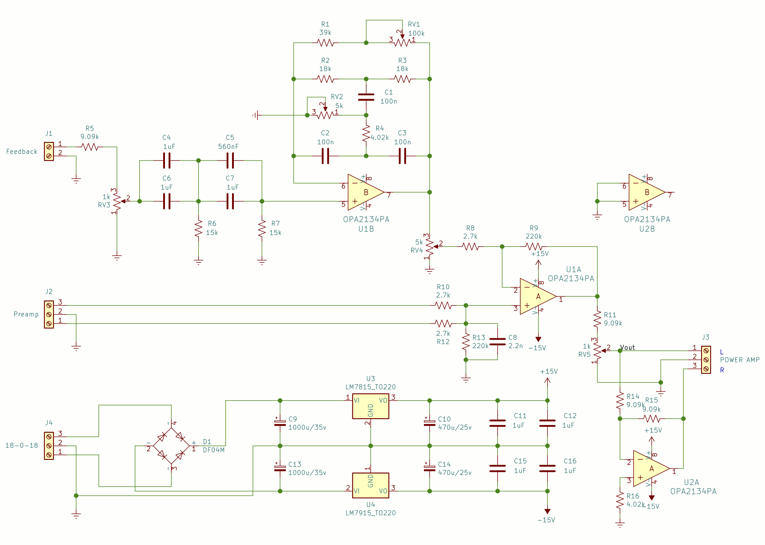
The circuit consists of two main parts - a special feedback filter and a differential amplifier. The feedback filter takes as input the output of the voice coil, which can be several volts. It must not overdrive the filter, so there is a pot to adjust it down to a reasonable level.
From there the signal goes to the differential amplifier, where it is subtracted from the sum of the two preamp channels. The output from the differential amplifier is the error voltage, which drives the power amplifier. In practice, the preamp channels come from the crossover already frequency limited. In fact, it is a requirement. The feedback will only work below about 400Hz, best case, and the crossover needs to be well below that.
C4-C7 along with R6 and R7 form a 2-stage high pass filter, one with an f3 of 5.3Hz, and one with 6.8Hz which keeps the feedback lower from 10Hz to 30Hz, and so raises the SPL in that area just a little.
The notch filter in OpAmp U1B's feedback loop is there to remove that artifact described above. It has to be boosted in the area where it is low, and a phase shift added to get the phase back in control. The filter is a twin-T filter with Q adjustment added. Because the Q adjustment sneaks the frequency up a bit, the fC of the filter is at 130Hz, while the anomaly is at 146Hz. After tuning, the notch is in the 146Hz area. The output of this section, taken off of trimmer pot RV4, is the compensated feedback signal. The filter amp has a gain of about 12dB outside the notch and 24dB inside.
U1A is a combination summing amplifier and differential amplifier. It sums the two input channels into a single mono signal, and subtracts the feedback from that. It also has a 1st order low pass filter with an fC of 220Hz. The overall gain of the differential amplifier is 82.
OpAmp U2A is an inverter to give an out-of-phase channel for bridging a stereo amplifier, which is the way I use it. If you are going to build one, and you are planning on bridging, test and calibrate using the bridged amp. It more than doubles the power to the speaker, so the feedback will be much higher for a given input voltage.
Results
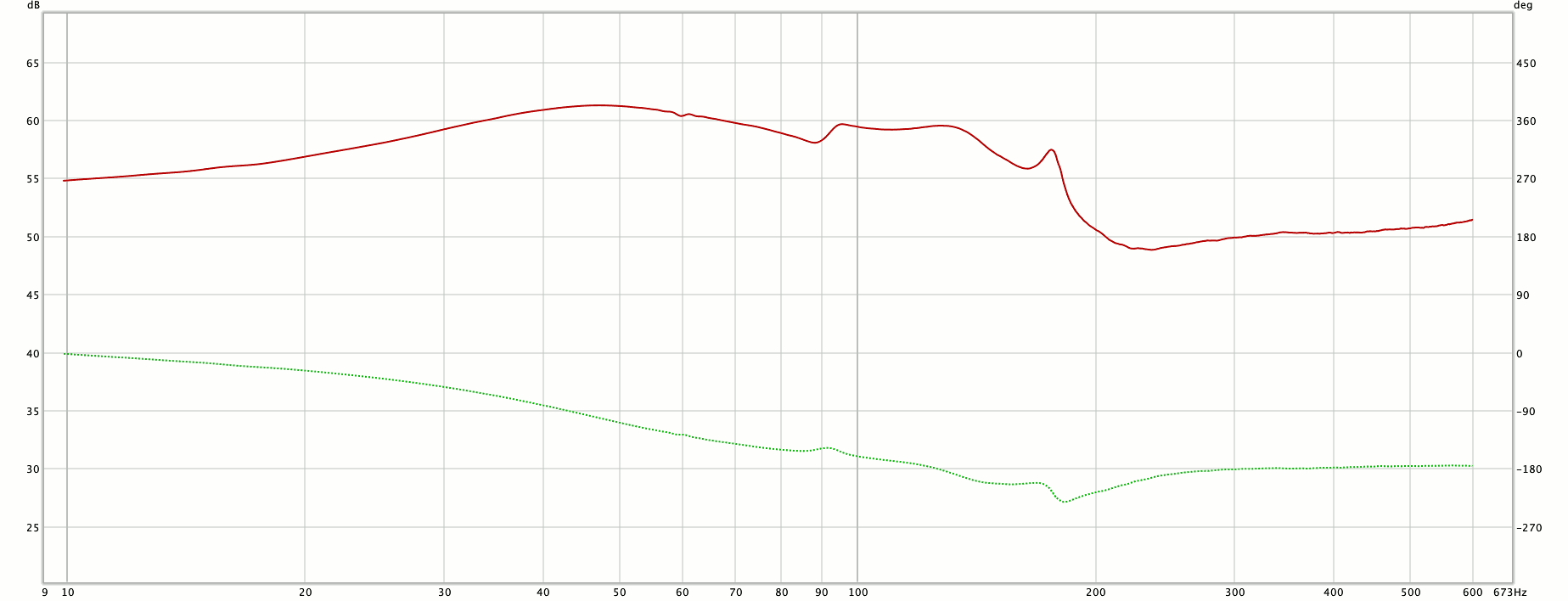
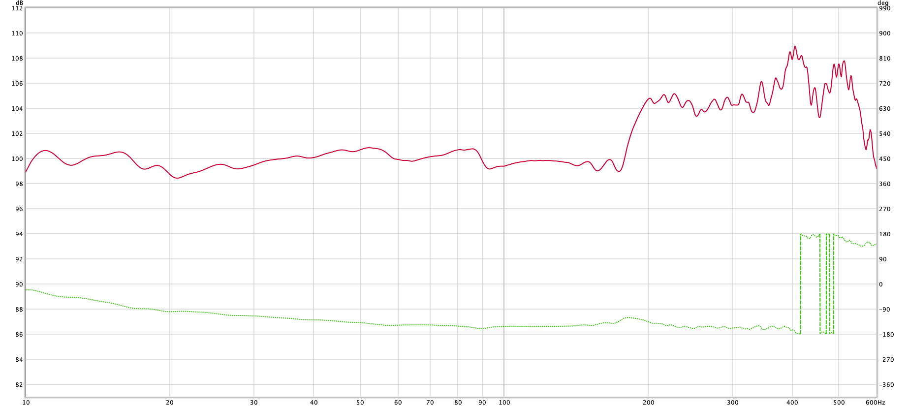
REW was used to measure the feedback response again, this time at the output of the feedback compensator, resulting in the plot to the left. This plot is really only for curiosity - the filter was tuned using the curve of the speaker output, with the error signal driving the amplifier.
REW was used to create a plot of the driver in the enclosure, with velocity feedback. The plot is to the left. It measures ±1.265dB (2.53dB p-p) from 10Hz to 180Hz. The crossover was required to be at 70Hz before this experiment, but now I have moved it to 85Hz to get above the 63Hz f3 of the main woofers.
What about that junk above 180Hz? It is an artifact of the driver, exacerbated by the lower feedback above 170Hz. I have a 48dB/octave LR crossover at 85Hz which effectively reduces that. It will be -51dB at 170Hz.
Fine Print
It can't be all good all the time. A 10" driver can only move so much air, so it can only get so loud at any given frequency. When you exceed that loudness, the driver gets nonlinear, causing a flat spot on the feedback. The amp will push at full power to try to get the driver to move farther. It makes a very loud click noise as it applies full power to the driver. There is no way around the physics of it. If you need to go lower and/or louder, you need a bigger cone or more of them. That is always true, but with velocity feedback it is more obvious when your woofer gets overextended, since it won't go gracefully nonlinear.
Also, although harmonic distortion is generally improved by a factor of 2 to 3 above resonance, it is considerable below resonance. Not as much as trying to get 13Hz out of a 26Hz driver without feedback, but bad enough.
Finished Board
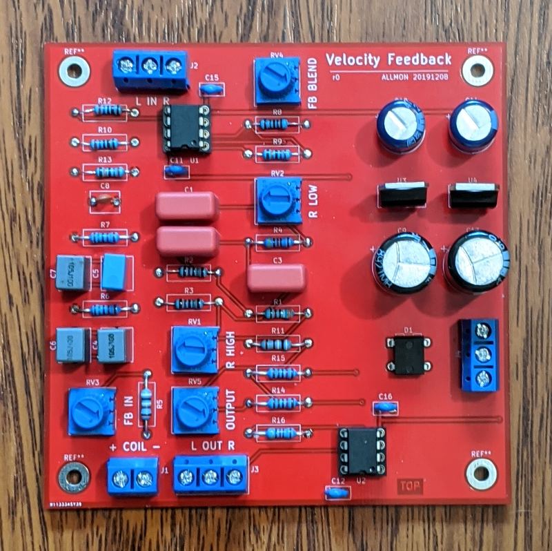
I built the finished VFB circuit on a 100mm x 100mm PCB. This is a picture of the final board. It goes in the subwoofer amplifier case, between the input and the amplifier, and connects to one voice coil of the driver. I set RV1 and RV2 to the middle of their range, and the rest to the bottoms of their ranges. That way it comes up safe. RV3 and RV4 get opened just a crack, followed by RV5. The subwoofer operates at that point, but much trial-and-error calibration is required.
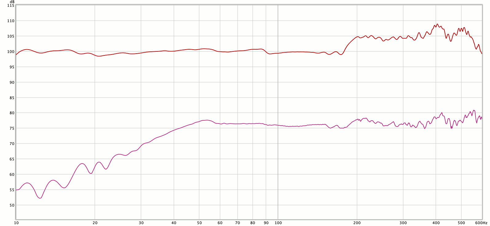
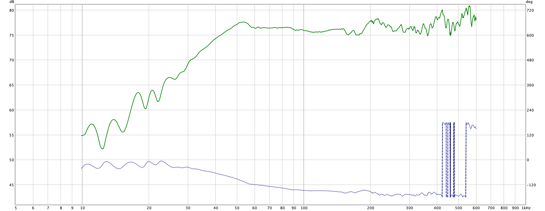
The bottom trace is the subwoofer frequency response before velocity feedback. It has the familiar drop-off at the box resonance. The top trace is the subwoofer frequency response after velocity feedback was added. It is pretty flat down to 10Hz. The amplitude difference is just so both traces show.
(No smoothing is applied to the graphs on this page)
Listening
With the room resonances mostly tamed using the MiniDSPs, the only thing left to do was listen to some music. I have a set of songs that really challenge the speakers at specific ranges. I tried them out on the new circuit and think the flatness of the subwoofer makes it impossible to tell there is a sub at all.
The extended response makes it clear that there are low frequencies in most recordings. I'm running the sub a little lower than the woofers, maybe 2-3dB, because of room resonances, and it just sounds fantastic. Kick drums sound like kick drums - not just generic thumps. With the 85Hz crossover the sub is handling the bottom octave of a 4-string bass guitar, and 1.5 octaves of a bass fiddle or 5-string bass guitar, and they sound very realistic. The sound doesn't localize to either the woofers or the sub woofer, so the soundstage appears to be intact. I wasn't certain it would be, what with all the electronic hocus-pocus going on in the filter board.
1. Radcliff, Clark J., Gogate, Sachin D. (1996) "Velocity Feedback Compensation of Electromechanical Speakers for Acoustic Applications"