High Power Loads for Arduino
If you need to drive something from a higher voltage than 5VDC, or supply more than 40mA, you are going to need something to help the Arduino out. If you are using a Due, or Teensy LC/3.1/3.2 you may find the output voltage is 3.3V, and the current as low as 5mA. But there are several ways to get around these limitations.
Direct MOSFET
If you have a 5V output, and you aren't trying to drive a high current load, you can drive some MOSFETs directly from the I/O port on the Arduino.
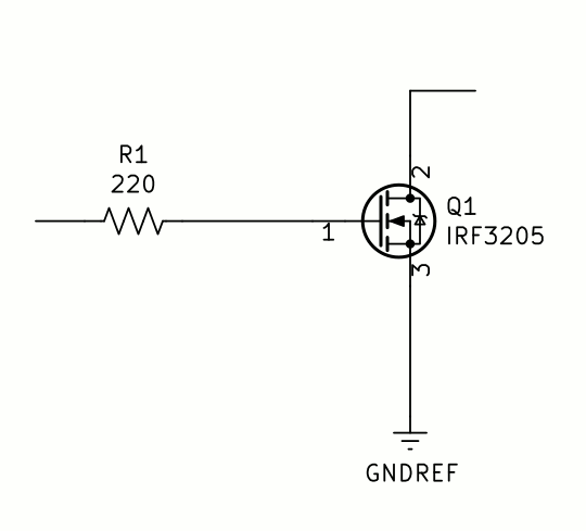
5V will turn on an IRF3205, but it won't turn it on very far. It has a Vgs(th) of 4V. To turn it all of the way on would take 12V on the gate. It will do for loads up to half an amp or so, though. You could drive an LED string, or a small automotive light bulb, or even a small relay. If you have a 3.3V output, you will have to use a logic level MOSFET, or one of the solutions below.
There are 5V (logic level) MOSFET switches that will turn on with a 5V input. An example is the IRL series from International Rectifier. They have a Vgs(th) spec of 2.5V, meaning they will start to come on at 2.5V, while the Nexperia BUK98150-55A/CUF has a Vgs(th) of only 1V, and will conduct up to 15 amps at Vgs=5V.
Darlington Transistor Arrays
One solution is to use an external Darlington array, such as the ULN2003A, or the ULQ2803A, to drive the high current device. Since they are open-collector transistors, you can pull the outputs up to any voltage you need within the 50V output voltage range.
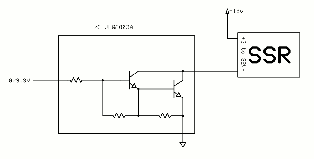
Although you can drive an SSR directly from the ATmega328 on the Arduino Uno, you can't from a Teensy LC. To do that you need to buffer the signal so it can provide more voltage and more current. This example shows a single darlington from a ULQ2803 driving a solid state relay which is connected to +12 volts. The SSR may be a DC or an AC relay, and may be capable of handling from 2 or 3 to several hundred amps. Writing a "0" to the port pin turns the SSR off, while writing a "1" turns it on.
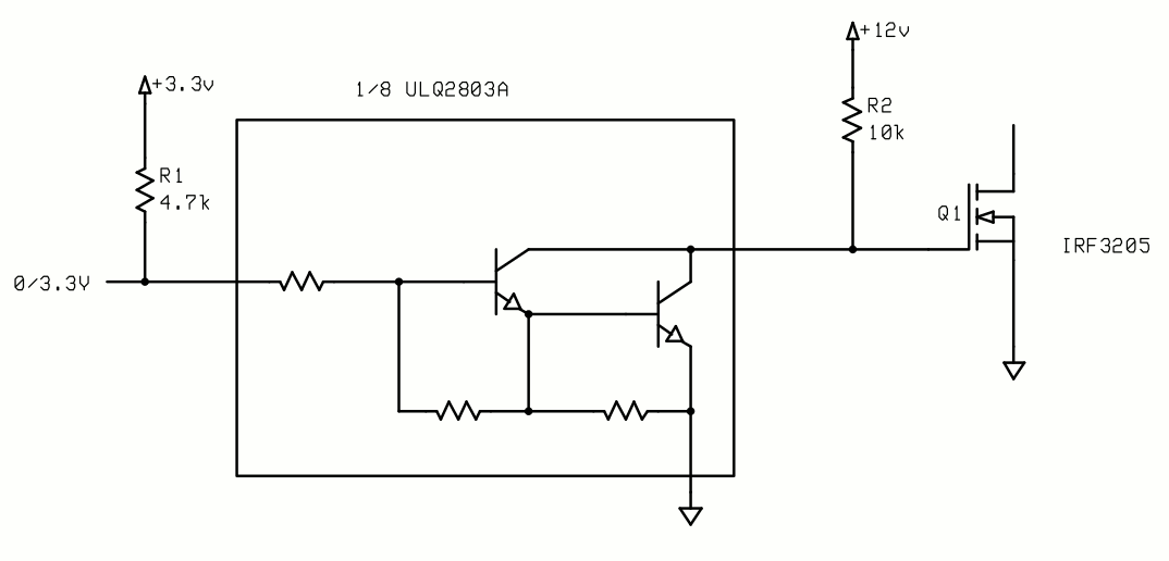
In this example the same darlington transistor array is used to drive a MOSFET, which itself would drive a heavier load at higher voltage and/or current. Resistor R1 insures the darlington is turned on and the MOSFET off on power up. R2 provides the turn-on voltage for the MOSFET. Writing a "0" to the port pin turns the MOSFET on, while writing a "1" turns it off.
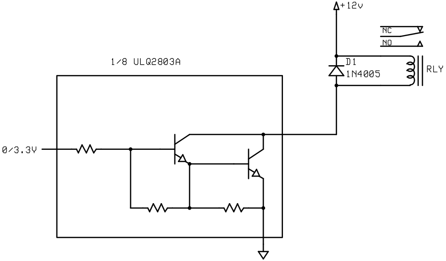
If the relay is small enough, you could drive it directly with the darlington array. A word of caution: the built-in free-wheeling diode connected to each darlington's collector is not sufficient for anything but the smallest relays, and I recommend always including the diode across the relay coil for safety. It will protect the darlington array from damage. Writing a "0" to the port pin turns the relay off, while writing a "1" turns it on.
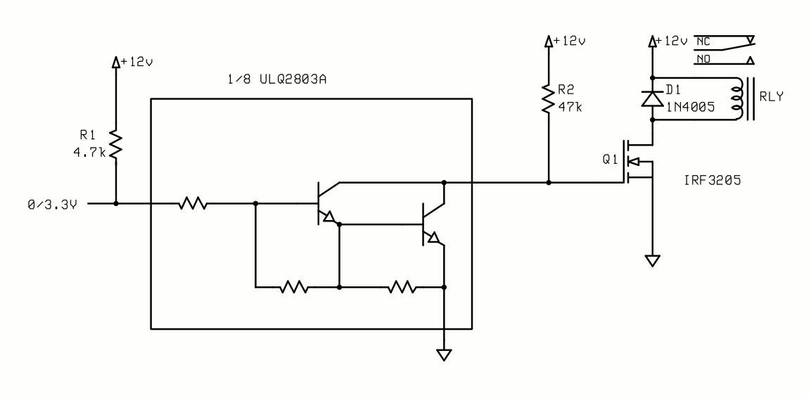
For larger relays it might be practical to combine the two circuits, with the MOSFET driving the relay. The output of the 12VDC power supply must be enough to supply all of the relays that will be energized at the same time. Small PC mount relays typically draw around 35 to 70mA @ 12VDC so plan accordingly. You can, of course, use any relay having a DC coil voltage less than the rated voltage of the MOSFET. Writing a "0" to the port pin turns the relay on, while writing a "1" turns it off.

For purely DC loads of up to 8 amps continuous, the BTS5012 high-side switch allows you to switch anything from 5.5V to 20V on and off like a switch. They are used extensively in automotive applications. They are current operated, and need a small signal bipolar or MOSFET transistor to trigger them because of the higher voltage on the trigger input. They also have a current sense output, so you can actively monitor the current through the device. A high on the base of the transistor turns the switch on and allows current to flow. There are also smaller 5V devices that are intended to switch USB port power on and off, but could be used anywhere you need to switch 5V.
Real-World Examples
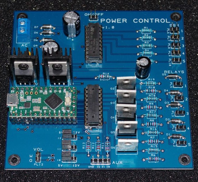
This board is a general purpose output board for interfacing to higher powered loads. It has five darlington outputs, five MOSFET outputs, and three 5V or 12V selectable open collector outputs (from the darlingtons). The darlington outputs are for non-inductive loads, like SSRs or LEDs.
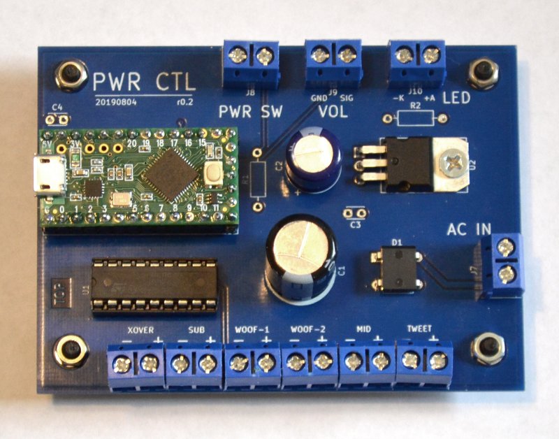
This board is an example of a specialized output board. It was designed specifically to drive SSRs to control a set of audio power amplifiers. It has six darlington outputs that drive SSRs to control 115VAC power to the amps. It runs on 9VAC input, and responds to the push of a power switch to trigger either a power up sequence or a power down sequence.