Small Telescope Flat Field Panel
A store-bought flat field panel for an 81mm scope (4.125" outside diameter) is relatively expensive. The Flat-Man-Gen2, for OTAs up to 8-1/8", is $375.00. I'm not completely adverse to spending money, but I like doing it myself more than spending money. I had such a great experience with the Ellumiglow 14" circle that I had to go with their 5" circle for the GT81.
The default inverter was a cheap one. Too cheap. Both pots broke while I was testing it. And it runs on 9V, which I don't have on the scope. I have since purchased a 12V "PWM" model, which is much better.
PWM in this context means you can PWM chop the power input to the inverter, and the inverter dims the panel. That is exactly what I was doing before, and still do with the 14" flat panel. The difference is that I chopped the ground on the old ones. It made it much simpler to do. I've since had some experience with high-side switches, and decided to give that a go for this new PWM inverter. Electrically the two methods are identical, from the inverter's point of view.
This is a how-to on the Ellumiglow 5" kit, which I built some time back. The new kit currently goes for $72.99 with a diffuser and the upgraded inverter.
Ellumigllow sells the 5" panel by itself for $32.99 plus shipping. You might be able to save a little by getting the 5" circle from Technolight.com. The Ellumiglow circle I have says Technolight on the back, and Technolight sells it for $22.50. Add the Ellumiglow EOE276 inverter at $24.99 ($37.77 delivered in the US), and you have a kit minus diffuser for around $60.00. I'm still playing with another inverter, from glowhut.com, which costs $9.00 ($14.00 delivered in the US) and is about equivalent to the Ellumiglow inverter. It looks like it works well. I'm using it now. The Technolight panel and the Glow Hut inverter would set you back $31.50 plus whatever the shipping turns out to be. Ellumiglow's equivalent is $62.99 plus shipping. I like Ellumiglow - they are good folks to do business with - but $30.00 is $30.00.
A piece of white paper or milky translucent stencil material will work as a diffuser. Mine has a sheet of stencil material and a neutral density filter to get flat field exposures up around two seconds. The panel is bright, from an astrophotography point of view. The neutral density gel filter sheets came from Adorama. I would recommend stacking 0.3 ND discs to start, or use a 0.6 ND disc. You can get about 12 discs out of a 21" x 24" sheet of filter material. You might need one to four discs, depending on telescope and the camera. Then you just need to pick an exposure time that fits all of your filters.
Inverter PWM Controller
The PWM controller is an Arduino Nano V3, driving a high-side switch to PWM 12Vdc to the inverter, thereby controlling the brightness. The Arduino firmware emulates a Pegasus FlatMaster. I initially had the hardware and firmware designed to use 8-bit PWM, since that is the resolution of the input data. That turned out to be the wrong thing to do, because the inverter + EL panel is more responsive at low levels than at high levels, making the brightness changes too big at the low end, and too small at the high end. I changed to 16-bit PWM, and built a lookup table of optimized PWM values.
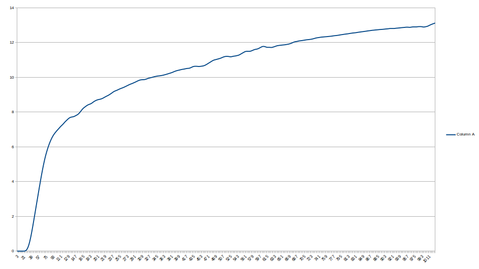
The EL panel response looks pretty bad. Too responsive at first, then flattening out at the high end. I built the response curve using the Nano and a calibrated photoresistor, running from 0 to 65535 4 ADU at a time, and reading the lux value from the photoresistor. The result is very non-linear.
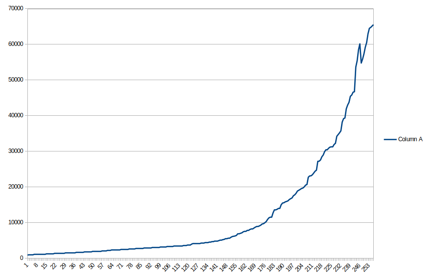
The way to get a linear output is to drive the inverter with a non-linear PWM signal. This graph shows the lookup table values that drive the output. The x-axis is 0 to 255, representing the brightness value desired. The y-axis is the 16-bit PWM value required to get that brightness. There was a lot of noise on the response, regardless of averaging and delays, so I wound up writing a program that has the Arduino calculate everything and build its own lookup table. It took about 35 minutes to run to completion, and then spit out the 256 16-bit PWM values.
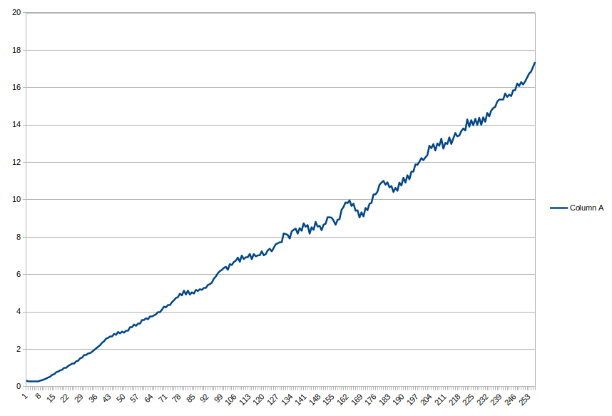
Lastly, I modified the program to just run a sweep from 0 to 255 using the lookup table, and output the lux values, which produced this chart. The light output ended up much more linear than it started. That should make it easier to determine how much change is required to affect a change in the value of the flat. If, for example, you want twice the ADU and you are at 25%, then 50% should get you in the ballpark. The steps may appear to the eye to be smaller at the top, but the light intensity is meant to be consumed by a camera, which is linear, as opposed to our eyes, which are not. There will, of course, be differences in every combination of controller, inverter and EL panel which are impossible to plan for.

The Arduino Nano uses one pin to drive a transistor. The transistor pulls the IN line down on the high-side switch, and power goes to the EL inverter. When the transistor is shut off by the Arduino, the high-side switch is shut off, and the power to the inverter is also shut off. It does this 490 times per second. The capacitor, C1, averages the pulses into a flatter signal. Diode D1 prevents the LED coming on, should the power cable get plugged into the PWM output connector. The LED will only turn on when the power cable is plugged into the input jack.
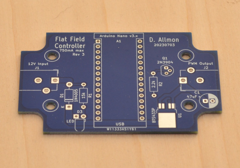
I got the PC boards from PCBWay.com. The boards were low cost, at $26 for 10 boards delivered to the US. I always use PCBWay for PC boards, because I get high quality boards for a low price. I've never had a poorly made board from them. I used to help out a friend who owned a PCB shop, keeping the electronics in his NC machines running. The PC boards he made were great - as good as any at the time - but they can't hold a candle to the boards I get from PCBWay these days. The technology has come a long way, and PCBWay is at the forefront. I don't know of any better value anywhere. I recommend them for your PC board needs.
The board went through one revision when I changed from 8-bit to 16-bit PWM, and another when I added a 100µF capacitor and removed a diode. Why all the boards? That BTS443P chip. It's surface mount, and a high power device. Hard to breadboard. What I should do for the future is cut one of these little boards in half, and add wires to it, so I could use the BTS443P with a breadboard.
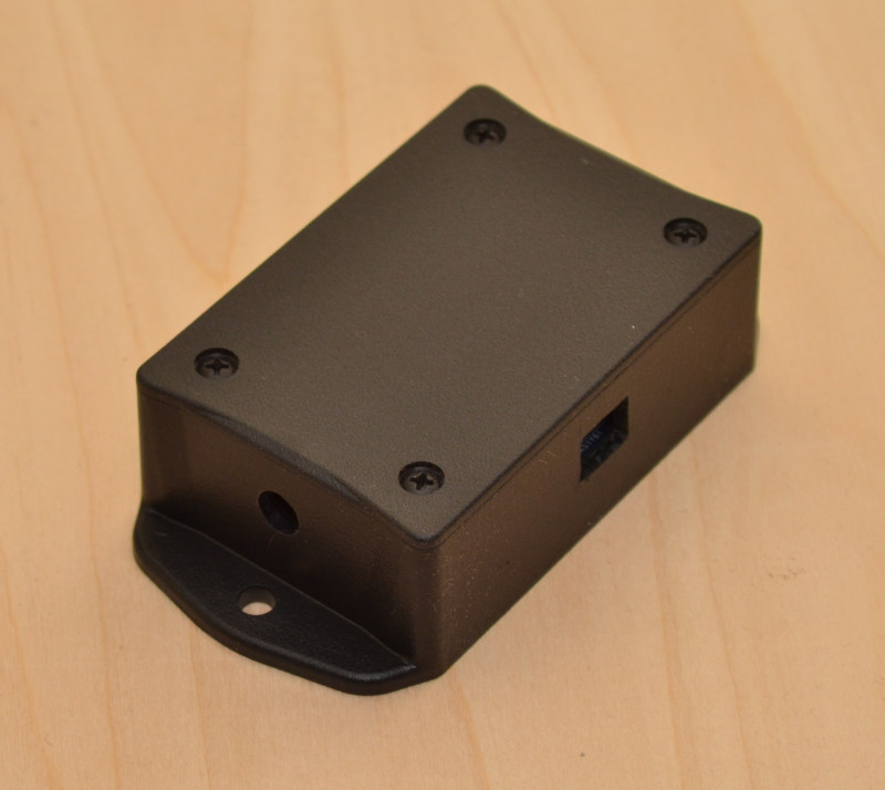
The board is 1.8" x 2.8" and has notches cut out to fit a PolyCase BT-2310 plastic box. I didn't fully appreciate how small the box and therefore the PC board would be at the time I ordered it. I just based it on the length of the Arduino Nano V3. The larger parts would only fit in certain places. There just isn't enough room between the screw holes. That's why power in and power out are at either end, rather than beside the USB connector. But the boxes get too big from there up, jumping to 3" x 4", the first size that will handle the connectors on one side. That's twice the size of this box.
Polycase has excellent documentation on their enclosures, including the required size and shape of any PC board you would need to make. The boxes were $3.18 each plus shipping.
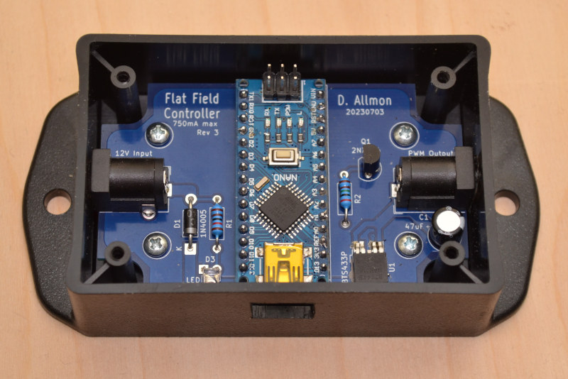
The parts are all mounted on the PC board. The only troublesome part is the BTS443P, which requires soldering with either a hefty, but small-tipped soldering iron or a hot air solder tool. I've used both with success. It had to be placed first, since soldering it later would be problematic with a hot air tool.
The Arduino Nano is not socketed. It's soldered directly to the board. It wouldn't fit any other way. It's too tall. It is unlikely to fail, unless the BTS443P shorts 12V to the IN pin, and the transistor shorts collector to base. I tested the pins on the BTS443P to make sure there were no shorts before soldering the Arduino in place. I also only soldered the 3 pins that are actually used - 2 grounds and one signal, so it is still possible to remove it, although not easy. If it was socketed, and the above scenario played out, the Arduino would still be fried, as would the surface mount switch, and the whole board would still need to be replaced.
Anyway, it all fit in the little box, with room to spare. The red LED comes on when you plug the power cable into the correct jack. I know it is considered unfriendly to have lights all over the place, but I'm making flats - I'm already annoying everyone around me. The LED helps me know where to spend my time troubleshooting, should things not work. I chose a large value limiting resistor, so it wouldn't be so bright. The LED also does not have its own hole, but lights up the inside, which is visible if the USB cable is not plugged in.
/*
 * Pegasus FlatMaster clone using Arduino Nano and an EL panel
 * Commands:
 * ACK "#\n"
 * VER "V\n"
 * ENABLE "E:n\n" (E:0 = off E:1 = on)
 * LEVEL "L:nnn\n" (L:20 is brightest, L:255 is dimmest)
 *
 */
#define CMD_ACK '#'
#define CMD_ENABLE 'E'
#define CMD_LEVEL 'L'
#define CMD_FIRMWARE 'V'
#define ACK_RESPONSE "OK_FM\n"
#define V_RESPONSE "V:2.0\n"
#define LIGHT_CTL 10

int brightness = 0;
bool enabled = false;
char inbuf[16];
int incursor = 0;
uint16_t icr = 0xffff;
uint16_t lookup[256] = {
    832, 888, 922, 934, 978, 1006, 1012, 1040, 1062, 1104, 1110, 1116, 1146, 1162, 1170, 1190,
    1200, 1210, 1230, 1260, 1270, 1282, 1310, 1328, 1348, 1376, 1378, 1380, 1482, 1484, 1488, 1492,
    1494, 1496, 1498, 1538, 1556, 1578, 1580, 1596, 1628, 1630, 1642, 1644, 1668, 1710, 1720, 1766,
    1774, 1790, 1814, 1828, 1850, 1870, 1908, 1920, 1932, 1948, 1954, 1960, 1982, 1996, 2000, 2036,
    2060, 2068, 2086, 2112, 2126, 2140, 2152, 2164, 2192, 2202, 2220, 2228, 2244, 2256, 2294, 2320,
    2372, 2400, 2414, 2464, 2492, 2504, 2518, 2540, 2556, 2582, 2598, 2612, 2636, 2652, 2690, 2692,
    2722, 2738, 2774, 2812, 2814, 2828, 2866, 2868, 2880, 2882, 2896, 2974, 2976, 3000, 3016, 3054,
    3070, 3110, 3134, 3174, 3176, 3188, 3244, 3246, 3308, 3318, 3320, 3334, 3336, 3350, 3386, 3426,
    3428, 3466, 3468, 3508, 3600, 3636, 3676, 3678, 3728, 3756, 3822, 3832, 3858, 3860, 4148, 4156,
    4224, 4226, 4276, 4278, 4328, 4356, 4470, 4498, 4560, 4588, 4640, 4818, 4870, 5092, 5154, 5426,
    5642, 5734, 5796, 5824, 6040, 6068, 6094, 6376, 6594, 6722, 6812, 6888, 7234, 7362, 7554, 7656,
    7720, 7784, 8398, 8858, 9088, 9140, 9460, 9768, 10486, 10512, 10640, 10846, 11000, 11720, 11978, 12326,
    12804, 13062, 13152, 13488, 13566, 13902, 14252, 14810, 15548, 15730, 15782, 16188, 16344, 16524, 16566, 17020,
    17114, 17688, 17712, 17780, 18460, 18798, 18984, 19796, 19822, 19980, 20830, 21738, 21896, 21988, 22080, 22290,
    23026, 25290, 25988, 26094, 26740, 27546, 27982, 28588, 28892, 28974, 29288, 29486, 29764, 30414, 30612, 32242,
    32284, 32576, 32892, 32972, 34710, 35108, 36516, 36888, 38894, 39334, 40716, 41406, 42202, 42894, 53426, 65535
};

void setup() {

    Serial.begin(9600);

    // for PWM frequency of 488 Hz on D9 & D10.
    setupPWM16();
    memset(inbuf, 0, sizeof(inbuf));
}

void setupPWM16() {
    DDRB |= _BV(PB1) | _BV(PB2); //Set pins as outputs
    TCCR1A = _BV(COM1A1) | _BV(COM1B1) //Non-Inv PWM
    | _BV(WGM11); // Mode 14: Fast PWM, TOP=ICR1
    TCCR1B = _BV(WGM13) | _BV(WGM12)
    | _BV(CS10); // Prescaler 1
    ICR1 = icr; // TOP counter value (Relieving OCR1A*)
}

//* 16-bit version of analogWrite(). Only for D9 & D10
void analogWrite16(uint8_t pin, uint16_t val)
{
    switch (pin) {
        case 9: OCR1A = val; break;
        case 10: OCR1B = val; break;
    }
}
void loop() {
    uint8_t ch;
    int bright;

    if (Serial.available()) {
        ch = Serial.read();
        inbuf[incursor++] = ch;
        if (incursor == sizeof(inbuf)) {
            incursor = sizeof(inbuf) - 1;
        }
        if (ch == 0x0a) {
          incursor = 0;
            // End character received.
            switch (inbuf[0]) {
                case CMD_ACK:
                    Serial.print(ACK_RESPONSE);
                    break;

                case CMD_ENABLE:
                    enabled = (inbuf[2] == '1')?true:false;
                    if (enabled) {
                        analogWrite16(LIGHT_CTL, lookup[brightness]);
                    } else {
                        analogWrite16(LIGHT_CTL, 0);
                    }
                    Serial.print(inbuf);
                    break;

                case CMD_LEVEL:
                    // Brightness is 255 (dim) to 20 (brightest).
                    // The PWM circuit uses 916 (dim) to 65535 (bright)
                    brightness = ceil(1.085 * (255 - atoi(inbuf+2)));
                    if (brightness > 255) {
                        brightness = 255;
                    } else if (brightness < 0) {
                        brightness = 0;
                    }
                    if (enabled) {
                        analogWrite16(LIGHT_CTL, lookup[brightness]);
                    } else {
                        analogWrite16(LIGHT_CTL, 0);
                    }
                    Serial.print(inbuf);
                    break;

                case CMD_FIRMWARE:
                    Serial.print(V_RESPONSE);
                    break;

                default:
                    break;
            }
            memset(inbuf, 0, sizeof(inbuf));
        }
    }
}
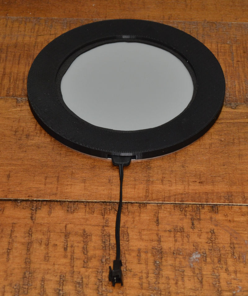
The Panel
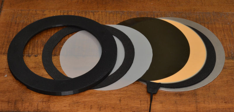
You could, I suppose, just point the scope up and lay the EL panel on the end of the tube, but it weighs nothing, so the cable would pull it off. The solution is to give it a rigid, somewhat heavy backing plate, and a rim that will keep it on the scope. For the backing plate, I went to ebay.com and picked up a 6" diameter, 0.063" thick aluminum circle. The rim is a 3D printed thing that doubles as a clamp, keeping the sandwich of aluminum plate, 2mm EVA foam, EL panel, ND filter and diffuser firmly in one stack. Six #6-32 screws around the perimeter hold the stack together. The sheet parts, including the EVA foam, were all trimmed to 5.25" diameter, to match the EL panel, using the acrylic diffuser as a template.
As a guide, a 0.6 ND gel filter will increase the exposure time by 4x. 2 layers = 16x. Sounds like a lot, but the exposure time with no filter would be very much less than a second. 1/8 second if I recall. This is with my camera. YMMV. I have a mechanical shutter, so longer exposures mean less variance due to shutter action. If you don't have access to any ND filter material, experiment with regular white printer paper. It acts to both dim and diffuse the light from the EL panel.
Here is a table of values for ND filters. The second table, about halfway down the page.

This is an SVG drawing, full size, of the back plate and the ring. Right-click and "Save image" to save it full size, or with Chrome, right click the image and select "Print". Under advanced options, set the scale to 100. I taped the drawing to the plate and the ring, and drilled them both at the same time. The ring was $33.00 from Xometry.com, but you could make it yourself for much less. The next project is a revamp of the 14" panel. I shudder to think of the cost of parts for that. I have about $130.00 invested in this 5" flat field panel project. Not a lot for a flat field panel, but still - it's only 6" across and a tiny bit more than 1/4" high.
You can tell from the cross section that the 3D printed ring overhangs the EL panel by quite a bit. I wasn't sure how much would be needed, so I used most of what was available, leaving room for the scope's dew shield. In hindsight, I should have made the overhang smaller, and would recommend to anyone tackling this project to do the same.
Use
To make a set of flats, I set the exposure to 2 seconds, and adjust the brightness for each filter to give around 32k ADU average. The flats all use the same darks, so it saves me time - in both imaging and processing.
The 16-bit PWM code came from an article by T.K.Hareendran, found on Codrey.com