Computerized Telescope Power Distribution Box V3
Skip to the end: Power Box 5
I've built two different power distribution boxes. The first was just a set of 6 jacks to provide power to the various devices. The second one was controlled via USB connection from the Raspberry Pi. I could turn any of the 6 channels independently on or off, and it added 2 temperature controlled heater jacks. It was a great improvement, but something it couldn't do was tell me how much current I was using. It was of no concern when I designed it, since I don't run from batteries. I was a bit short-sighted. It could have told me how much power would be needed if the scope did run from batteries, or if it was even feasible to try. It could have told me if my power supply was too big, too small, or just right.
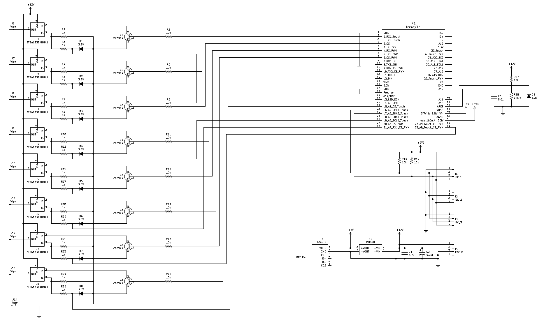
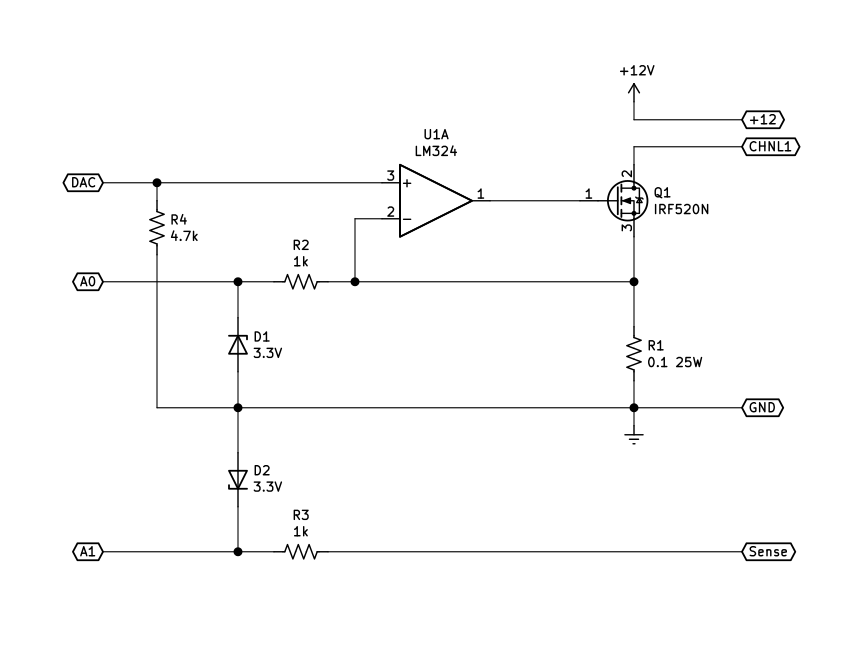
NOTE: This design is not recommended. If a short circuit develops on one of the output channels, it will put 12V on the top of a 3.3V zener through a 1kΩ resistor, and the resulting zener voltage will exceed the maximum allowed voltage on the analog input pin, smoking the Teensy. Refer to Power Box 4, or Power Box 5 instead. You could also just change the 1kΩ resistors that are in series with the zener diodes to 4.7kΩ and change the zeners to 2.0V. That might save the microcontroller in the event of a shorted output. But then you would have a stripped down power box 4.
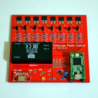
So I've made some changes to the design and a new PCB. Electronically it is basically the same as v2, but uses better switches, a better MCU (the Teensy 3.2), and utilizes the current sense outputs of the switches to monitor actual current being drawn by the scope and its peripherals.
I intentionally didn't look at existing power boxes because I didn't want to just clone something. I wanted to build something to fill my needs. To that end, 8 ports, up to 8A each (20A max total), all switched. The ability to set any ports to auto-on so they will come on at power up. The current is monitored on all 8 ports, as is the input voltage. The only thing not monitored is the DC-DC converter that powers the Raspberry Pi, which should be a pretty constant draw of 1.45A.
Although there is a little more circuitry on the board, the board is about 30% smaller than v2. I added some resistors and zener diodes, and a larger MCU, but used smaller parts where I could, and used up some real estate left open on the v2 board. There is no external EEPROM, since the Teensy 3.2 has a 2kx8 internal EEPROM.
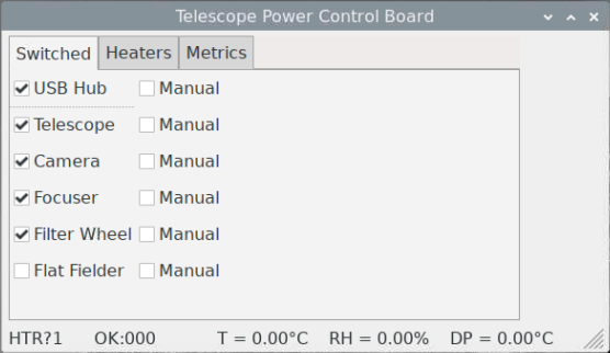
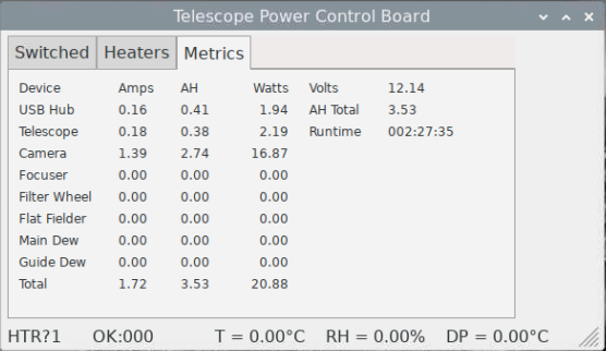
The computer interface required some additional commands to get the current, power, and amp hours from each port, and the total current and amp hours. The Python program that interacts with the box has been changed to add a page for the power metrics.
Parts
| Item | Description | Needed/Bought | Price |
|---|---|---|---|
| MDS20A05 | Meanwell 5V 4A DC-DC converter | 1/0 | 40.06 |
| 712AH | Switchcraft 2.5mm x 5.5mm DC barrel socket | 6/0 | 20.22 |
| 4006H-6B | Context split-body aluminum enclosure 6.0" L x 4.13 W x 1.5622" H | 1/0 | 23.95 |
| - | PCB | 1/1 | 7.20 |
| TPSB475K035R0700 | AVX 4.7uF 35V Tantalum | 1/1 | 0.85 |
| CL31B475KBHNNNE | Vishay 4.7uF 50V Ceramic | 1/1 | 0.33 |
| 10kΩ 1/8W 1% | Resistor | 10/200 | 6.00 |
| 1kΩ 1/8W 1% | Resistor | 16/200 | 6.00 |
| 1.07kΩ 1/8W 1% | Resistor | 1/200 | 6.00 |
| 15kΩ 1/8W 1% | Resistor | 1/200 | 6.00 |
| BZX55B3V3 | Zener diode 3.3V | 8/25 | 3.73 |
| BTS6133DAUMA1 | Infineon high side switch | 8/10 | 25.80 |
| 2N3904 | NPN small signal transistor 30V TO92 | 8/10 | 3.15 |
| Teensy 3.2 | Teensy 3.1 or 3.2 Microcontroller board | 1/0 | 23.00 |
| BOB-15100 | Sparkfun USB-C breakout | 1/1 | 4.50 |
| Total | $180.00 |
Some of the parts were junk box parts, but most had to be bought. I bought 200 of each resistor value because that was the minimum for those parts (they're 1/8W and tiny). The Teensy I already had, along with the jacks, DC-DC converter, and enclosure from the first power box. I had to make a cutout the right size for the Teensy's USB micro B connector.
Arduino Power Box Source: pwrctl_teensy.zip
Python Control App source: pwrbox3.zip
You'll need to forgive me for using this project to learn wxPython. Both because it looks like a beginner did it, and because you would have to install wxPython to use the app.
Current Sensing
The high-side switches have current sense outputs. They push a current out of the pin proportional to the current in the main output. It is approximately 1/10000 of the output current, so 1A gives 0.1mA at the sense output. It produces 0.1V across the 1k sense resistor. 12A produces 1.2V. The ADC reference is set to 1.2V, so 4095 ADU = 12A, while 340 ADU = 1A. Of course it isn't that simple. That 1/10000 number is nominal (at -40°C). At different temperatures and output currents it has a different ratio. The data sheet goes into a little detail as to what the ratios might be, in a large range, but for any given part, the ratio is defined by a possibly unique, more-or-less fixed line. The part is intended to tell your car's computer when a taillight bulb is burned out - not necessarily track the current precisely.
To come up with an algorithm for calibrating the sense signal, I built a current sink similar to the one I used for characterizing solar panels. It used a MOSFET and a 0.1Ω 1% resistor to generate a known current. It measured the current through the high-side switch and the current indicated by the current sense output, making 100 readings at current levels from 0 to 8A.
Although the 1.2V reference limits the measurable range to 12A, for practical reasons I limited the current to a little under 8A in the test software. That's the nominal rating on the BTS6133D, and my test MOSFET is only good for 9.2A. The extra 4 amps range is because the hardware and firmware are easier with a 1k sense resistor and a 1.2V reference. And the switches can do more than 8A before current limiting. Max load current is 33A and current limit is 75A. The board would burn its traces off before it hit 33A. The design limit is 20A max total current, 8A max per channel.

This is a plot of the current sense before calibration (green), and after (red) as compared to the actual current (blue). This is for a single BTS6133D mounted on a test board. Compared to the BTS5012 I used on the previous version, the BTS6133D was a joy. The BTS6133D raw sense current was straight as an arrow. A little tweaking and it's perfect. The BTS5012 had hiccups and significant curvature in the sense output.
The raw sense value is ADU x 0.00292969, which accounts for the 1kΩ load, 1:10,000 ratio, and 12A full-scale range. The ratio is not exactly 1:10,000 or no calibration would be required. I used a multiplier of 1.114 to rotate the signal until it had the same slope as the actual current, and subtracted 0.23 to lower the signal to line it up almost exactly with the actual current. So:
Iraw = sense ADU x 0.00292969
Ical = Iraw x multiplier + adder
Ical = Iraw x 1.114 + (-0.23)
The error averages just under 2%. It's worse at low amperage, where noise and slope error are more significant, and much better at higher currents, where a small offset is not so significant. Each channel requires individual calibration. I made a harness for testing a single channel, and moved it to each of the eight channels in turn, testing with the MCU pulled from the board. For this test, I compiled the app with the multipliers all set to 1.0 and the adders to 0.0. The current sink was modified to calculate the slope and offset required to correct the signal. Then I transferred those results into the power box code, replacing the 1.0 and 0.0 values, and compiled the app again.
float calibration_mult_pwr[] = {1.041531, 1.065915, 1.078227, 1.065453, 1.043193, 1.048718, 1.037915, 1.049714};
float calibration_add_pwr[] = {-0.100586, -0.000732, -0.020508, -0.019287, -0.043701, 0.011475, -0.104248, -0.073975};
Voltage
The input voltage is measured right where the supply leads connect to the board. Voltage doesn't really matter much, since I don't have control over it, but the voltage reading under load can indicate problems with the power supply or wiring. For example, a voltage of 10.5V on a 12V lead acid battery would indicate 100% depth of discharge, while a large voltage drop when the camera is turned on could indicate a bad connection between the power box and the supply.
What is the result?
| Device | Current (typ.) | Current (max) |
|---|---|---|
| USB Hub | 0.17 | 0.22 |
| Telescope | 0.20 | 0.86 |
| Camera | 0.62 | 2.75 |
| Focuser | 0 | 0.20 |
| Filterwheel | 0 | 0.33 |
| Flat Fielder | 0 | 0.38 |
| Unused 1 | 0 | 0 |
| Unused 2 | 0 | 0 |
So amp hours per hour calculates up to average about 3 including the camera cool-down. The scope would use around 30AH in 10 hours. Divide by 0.8 to keep 20% charge in the battery and you get 37.5AH. Some math says a 40AH SLA (sealed lead acid) battery would do, with no headroom. There are 55AH SLA batteries available, so that is what I would use. It would take about 18.1 hours to completely discharge the battery, 14.4 hours to discharge to 20%.
After having used it for a while, I've noticed a pattern. I power up the power supply, which powers the RPi. Then I turn on the USB hub, so the peripherals have a USB connection to the RPi. The telescope uses a serial converter which is plugged into the hub. Then the telescope is powered on. I have a script that I use to initialize the LX600 for remote operation. Once that is run, I turn everything except the flat field panel on. So it looks like the "auto on" feature is not used at all.
A tragedy befell this power box. One of the very expensive Switchcraft DC power jacks shorted positive to ground. Using the best of my troubleshooting skills, I was unable to determine exactly how the Teensy was fried, since all of the supporting circuitry is working. If a zener diode opened, the sense voltage on that channel could go to 5V, cooking the Teensy, but the diode is not open. The Teensy, however, is completely fried. It isn't recognized at all by the computer. There are no Teensy 3.2 boards available, and there won't be until March 2023! Chip shortage. Fortunately, there are Teensy LC boards available, and that is what I used on the replacement for this power box.