Characterizing Solar Panels
Characterization of a solar panel, for the purposes of this project, means to graph the voltage vs. current for a range of currents, with an assumed even illumination. It may seem a little simple to expect that to tell us anything standard about the panels, but I don't want to know anything standard. I want to know how this particular panel behaves in this particular backyard. How much load can I give it before the voltage drops to a point that it can't be used?
This brings us to the maximum power point (MPP). On the graph below, the yellow line is the total power being generated by the panel. Power increases, but then falls off. It is not exactly coincident with the sharp voltage falloff, but is somewhere just above that point. In order to harvest the maximum power, you need to find that point. For this panel, it is 7.061V @ 76mA.

Voltage Controlled Current Sink
A simple pot could be used, but it isn't going to be nearly as easy to the control the current. With this circuit the Arduino just ramps the set point linearly, and measures the values of voltage and current. The accuracy is based on the precision of the current sensing resistor, R1. In my application, the total power generated by a single panel was about 0.534W.
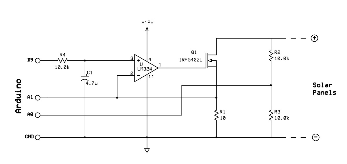
The Arduino sketch sets the setpoint on pin D9, waits 50mS for things to settle, and reads the voltage and current on A0 and A1. Then it writes it to the uSD card, for use later. The panel voltage is (5/1024)*ADU*2. (5/1024) is the voltage per ADU, and times 2 because the voltage divider cuts the voltage in half. The current in amps is (5/1024)*ADU/10. (5/1024) for the same reason, and divided by 10 because the resistor R1 is 10 ohms. The Arduino increments the PWM duty cycle from 0 to 100% in 256 intervals, causing the current to increase from 0mA to a maximum of 500mA in 1.95mA increments.
/*
 * Solar Panel Characterization
 *
 * This app uses a voltage controlled current sink circuit to
 * characterize solar panel performance with increasing load.
 */

#include <SPI.h>
#include <SD.h>

const int chipSelect = 8;

int pwmValue;
int currentPin = A1;
int voltagePin = A0;
int currentSink = 9;

File dataFile;

void setup()
{

  Serial.begin(9600);

  pinMode(chipSelect, OUTPUT);
  if (!SD.begin(chipSelect)) {
    Serial.println("Card not present.");

    // Halt!
    while(1);
  }
  Serial.println("Card initialized.");

  dataFile = SD.open("solar.csv", FILE_WRITE);
  if (!dataFile) {
    Serial.println("Error opening file on SD card.");

    // Halt!
    while(1);
  }

  String output = "PWM,VOLTAGE,CURRENT";
  dataFile.println(output);

  pwmValue = 0;
  analogWrite(currentSink, pwmValue);
}

void loop()
{

  // Set the current sink to the next level.
  analogWrite(currentSink, pwmValue);

  // Give it 50 milliseconds to stabilize.
  delay(50);

  // Read the voltage.
  int ADU = analogRead(voltagePin);
  float voltage = (5.0/1024.0)*ADU*2.0;

  // Read the current.
  ADU = analogRead(currentPin);
  float current = (5.0/1024.0)*ADU/10;

  // Make a csv string.
  String output = String(pwmValue) + "," + String(voltage,2) + "," + String(current,3);

  // Store the data on the SD card.

  // if the file is available, write to it:
  dataFile.println(output);

  // Adjust to the next level. Halt if > 255.
  if (++pwmValue == 256)
  {
    // Shutdown the current sink (the transistor could get very hot).
    analogWrite(currentSink, 0);

    // Close the file on the SD card.
    dataFile.close();

    // Let the user know it is finished.
    Serial.println("Done.");

    // Loop forever.
    while(1);
  }
}
The result is a CSV file containing all 256 pairs of values:
PWM,VOLTAGE,CURRENT
0,4.23,0.000
1,4.23,0.002
2,4.21,0.004
3,4.19,0.005
4,4.19,0.007
5,3.18,0.008
    .
    .
    .