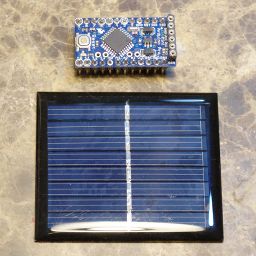
The Solar Uno project was fun, if not overly practical. The Arduino Pro Mini stands a much better chance of becoming a real application. This time we'll look at the 8MHz, 3.3V version. It has a 3.3V voltage regulator that can accept 3.4V to 12V input. The power source will be a single 4.2V AA-size lithium-ion battery that gets recharged by a solar panel. A charging circuit protects the battery from overcharge.
Pro Mini Voltage and Current Requirements
For this basic test, the blink sketch is used. It tells us two things:
- How much idle current there is, and
- How much current the LED takes.
| Vcc | Icc (Lo) | Icc (Hi) | Waste |
|---|---|---|---|
| 7.4V | 15mA | 20.7mA | 36mW |
| 3.7V | 4.1mA | 7.8mA | 1.6mW |
You can see that the 3.3V Pro Mini requires much less current than the 5V version. The 3.3V version runs at one half of the speed of the 5V version, but that will be plenty for this application. The baud rate on the serial port has to be cut in half, to 57.6kb. The 8MHz clocked ATmega328P can't keep up with 115.2kb. The LED on the 5V unit draws 5.7mA, but on the 3.3V version it only draws 3.7mA. The limiting resistors are the same 330Ω value on both versions. Why does this matter? Because the LED on the 3.3V version takes nearly 5 times as much power as the entire circuit will take when we're done with it.
The 3.3V Design
The first thing to find out is how much power is required. For that, the firmware needs to be roughly finished and the hardware in place. Testing the Arduino with the firmware will allow you to measure the current the circuit uses.
Code in this test application lowers the total current consumed by the Arduino Pro Mini, the RTC, and the µSD card to around 450µA average, then once per minute it spikes up to around 20mA for a fraction of a second while the µSD card is written. I've measured it at 2 to 5 mS at around 20mA. Assuming 5mS, that works out to a negligible 1.6µA additional average current. The Arduino current is 220µA. The RTC current is 110µA when the squarewave output is high and 120µA when the squarewave output is low. I removed the pullup resistors from the RTC to get the total current down to 100 - 120µA. I also pulled the LED off the RTC, and the power LED off of the Arduino Pro Mini. The µSD card draws about 100µA, so the circuit uses 450µA total.
Next you need to determine your solar power availability. Some locations have all of the sun they could ever need, while others have less than ideal conditions. To determine the situation at your location, see:
Daylight vs. Latitude and Sunshine by City. The first one will tell you how many sunny hours there might be in a day, and the second one will tell you what percentage are actually useful. The second link gives access to European cities as well, although the information is in "Sunny days per month" (sunny days ÷ days = %useful) You should come away from the two references above with a number which represents the number of effective hours of sunlight you can expect per day. Armed with this information you will be able to determine how big your panel(s) should be. The mAH you use needs to be replenished in the available sunny times. More on this below the code.
The idea is to start with the shortest day of the year, throw in a couple of cloudy days, and design for that. If you have lots of sun, like in Arizona or central California, you can use smaller panels. If you live in the northwest, you may need to size your panels such that they deliver the required current on an overcast day. The code will allow you to see if you've designed it right, by tracking the charging time during the day and battery droop overnight.
The Code
The code is just a simple 3-channel voltmeter and "smart" battery charger. It measures the solar panel, charger output, and battery voltage and writes them to a µSD card once per minute. There are a few power saving features, like the LowPower library. The LowPower library is just a really simple way to put the CPU to sleep. It replaces about 5 lines of code, so it is easier to read. You can see the specifics of the circuit, like the resistor dividers, charging circuit, etc., and more detail on how they are used on the Solar Arduino Uno. One important difference - the voltage dividers have been changed from a 10kΩ to a 100kΩ resistor and a 2kΩ to a 10kΩ potentiometer. That saves almost 300µA when running off of the battery.
// The timer0 interrupt is disabled, so the delay()
// functions will not work. Use _delay_ms() instead.
#include <SPI.h>
#include <SD.h>
#include <Wire.h>
#include <avr/power.h>
#include <avr/sleep.h>
#include <util/delay.h>
#include <LowPower.h>
#include "RTClib.h"

#define DS_3231
//#define DS_1307

#ifdef DS_3231
RTC_DS3231 rtc;
#else
RTC_DS1307 rtc;
#endif

#define V_PANEL A0
#define V_CHARGER A1
#define V_BATTERY A2
#define MIN_SOLAR (double)5.9
#define MAX_BATTERY (double)4.1
#define MIN_BATTERY (double)3.85

// Blips for one second every minute.
#define INDICATOR 3
#define INDICATOR_ON 1
#define INDICATOR_OFF 0

// Shuts down the charging circuit.
#define SHUTDOWN  4
#define SHUTDOWN_YES 1
#define SHUTDOWN_NO 0

#define SQUAREWAVE 2

// This is the mV at the battery/panel for one ADU:
// (15v / 1.1v) * (1.1v / 1024)
// 13.636363 * 0.00107421875
#define ADC_FACTOR (double)0.0146484375

// Change the chipSelect to match the CS you choose on
// your SD card module.
#define chipSelect 10

int ticker = 0;
char buf[40];
char tmpBuf[8];
double v_panel, v_charger, v_battery;
DateTime now;
char filename[] = {"solar.csv"};

/*****************************************************************************
 * isShutdown
 *
 * Reports on the state of the SHUTDOWN bit.
 *****************************************************************************/

bool isShutdown() {
  return digitalRead(SHUTDOWN)?true:false;
}

/*****************************************************************************
 * getSolarVoltage
 *
 * Returns the voltage on the solar panel.
 *****************************************************************************/

double getSolarVoltage() {
  return analogRead(V_PANEL) * ADC_FACTOR;
}

/*****************************************************************************
 * getChargerVoltage
 *
 * Returns the voltage on the charger output.
 *****************************************************************************/

double getChargerVoltage() {
  return analogRead(V_CHARGER) * ADC_FACTOR;
}

/*****************************************************************************
 * getBatteryVoltage
 *
 * Returns the voltage on the battery bus.
 *****************************************************************************/

double getBatteryVoltage() {
  return analogRead(V_BATTERY) * ADC_FACTOR;
}

/*****************************************************************************
 * saveReadings
 *
 * Reads the voltages off the analog pins and writes
 * them as a line in a CSV file on the SD card.
 *****************************************************************************/

void saveReadings() {

  if (!SD.begin(chipSelect)) {
    Serial.println("SD Card failure");
  }
  memset(buf, 0, sizeof(buf));
  sprintf(buf, "%4d-%02d-%02d %02d:%02d,",
    now.year(),
    now.month(),
    now.day(),
    now.hour(),
    now.minute()
  );
  // Read the panel voltage.
  v_panel = getSolarVoltage();

  // Read the battery voltage.
  v_battery = getBatteryVoltage();

  // Read the charger voltage.
  v_charger = getChargerVoltage();

  // Some icky string formatting.
  memset(tmpBuf, 0, sizeof(tmpBuf));
  dtostrf(v_panel, 6, 3, tmpBuf);
  strcat(buf, tmpBuf);
  strcat(buf, ",");

  memset(tmpBuf, 0, sizeof(tmpBuf));
  dtostrf(v_charger, 6, 3, tmpBuf);
  strcat(buf, tmpBuf);
  strcat(buf, ",");

  memset(tmpBuf, 0, sizeof(tmpBuf));
  dtostrf(v_battery, 6, 3, tmpBuf);
  strcat(buf, tmpBuf);
  strcat(buf, "\\n");
  Serial.print(buf);
  _delay_ms(7);

  File dataFile = SD.open(filename, FILE_WRITE);

  if (dataFile) {
    dataFile.print(buf);
    dataFile.close();
  } else {
    Serial.println("error opening " + (const)filename);
  }
}

/*****************************************************************************
 * setCharger
 *
 * Determines the correct state of the charging switch
 * based on the solar, charger, and battery voltages.
 *****************************************************************************/

void setCharger() {

  // Power supply maintenance.
  if (isShutdown()) {
    // The charger is shutdown. Just check the voltage and see
    // if it is lower than we want it to be.

    // Only charge if the sun is up.
    if (getSolarVoltage() > MIN_SOLAR) {
      if (v_battery < MIN_BATTERY) {
        // Turn the charger back on.
        digitalWrite(SHUTDOWN, SHUTDOWN_NO);
      }
    } else {
      // Save a milliamp and turn off the shutdown transistor.
      digitalWrite(SHUTDOWN, SHUTDOWN_NO);
    }
  } else {

    // If the sun is up...
    if (getSolarVoltage() > MIN_SOLAR) {

      // Shutdown the charger.
      digitalWrite(SHUTDOWN, SHUTDOWN_YES);

      // See if battery is charged.
      if (getBatteryVoltage() < MAX_BATTERY) {
        // Not charged - don't shut it down.
        digitalWrite(SHUTDOWN, SHUTDOWN_NO);
      }
    } else {
      digitalWrite(SHUTDOWN, SHUTDOWN_NO);
    }
  }
}

/*****************************************************************************
 * setup
 *
 * Initializes everything.
 *****************************************************************************/

void setup() {
  // Open serial port
  Serial.begin(57600);

  pinMode(SQUAREWAVE, INPUT);
  digitalWrite(SQUAREWAVE, 1);

  pinMode(INDICATOR, OUTPUT);
  digitalWrite(INDICATOR, INDICATOR_OFF);

  pinMode(SHUTDOWN, OUTPUT);
  digitalWrite(SHUTDOWN, SHUTDOWN_NO);

  pinMode(chipSelect, OUTPUT);

  // See if the SD card is present
  Serial.println("Check SD card");
  if (!SD.begin(chipSelect)) {
    Serial.println("SD Card failed, or not present");
    while (1);
  }
  Serial.println("SD Ok");

  // See if the RTC is present
  Serial.println("Check RTC");
  if (! rtc.begin()) {
    Serial.println("No response from RTC");
    while (1);
  }
  Serial.println("RTC Ok");

#ifdef DS_3231
  if (rtc.lostPower()) {
#else
  if (!rtc.isrunning()) {
#endif
    Serial.println("Set RTC time");
    rtc.adjust(DateTime(F(__DATE__), F(__TIME__)));
  }
#ifdef DS_3231
  rtc.writeSqwPinMode(DS3231_SquareWave1Hz);
#else
  rtc.writeSqwPinMode(SquareWave1HZ);
#endif

  now = rtc.now();
  ticker = now.second();
  Serial.print("Second: ");
  Serial.println(ticker);

  // Disable timer0
  TIMSK0 &= ~_BV(TOIE0);

  // Enable the interrupt as a falling edge.
  attachInterrupt(digitalPinToInterrupt(2), Int0, FALLING);

  // Change the reference to the 1.1V internal.
    analogReference(INTERNAL);

  // Clear out one read for the ADC reference change.
  analogRead(V_PANEL);

  // _delay_ms() to allow chrs to xmit before
  // the CPU goes to sleep.
  _delay_ms(10);
}

/*****************************************************************************
 * loop
 *
 * Main program loop
 *****************************************************************************/

void loop() {

  while(1) {
    LowPower.powerDown(SLEEP_FOREVER, ADC_OFF, BOD_OFF);

    // Just skip 58 seconds, but after that, read
    // the RTC to get the real second.
    if (++ticker > 58) {
      digitalWrite(INDICATOR, INDICATOR_ON);
      now = rtc.now();
      if (now.second() == 0) {
        ticker = 0;
        // Save the voltage readings to SD card.
        saveReadings();

        // Set the charging state.
        setCharger();
        digitalWrite(INDICATOR, INDICATOR_OFF);

        // Reset the ticker in case we ran over one second.
        now = rtc.now();
        ticker = now.second();
      }
    }
  }
}

// The Int0() just needs to be here - it doesn't have to do anything.
void Int0() {;}
Calculations
The amount of power we need to drive the Arduino Pro Mini for 24hrs, using the method from the Solar Powered Arduino Uno article, is 0.45mA x 24hrs = 10.8mAH per day. Since we intend to be able to run through two cloudy days, 32.4mAH may be required. This is the number of mAH that must be supplied by the solar panel in your hours of usable daylight. In Louisville, KY, there are 9.17 hours of daylight on December 21st. Only 56% of the sunlight in Louisville makes it to our panels, so 5.14 effective hours of sunlight. The required charge rate is 32.4mAH / 5.14H = 6.3mA per hour. If the panel can deliver that, on December 21st, then it should be a good match. If you aren't designing your project on December 21st, just look to see that the battery is charged in less than the number of hours you have calculated. In practice, the panel will charge the battery as fast as it can, so if the panel puts out 100mA, it will put it all into the battery, charging it very quickly.
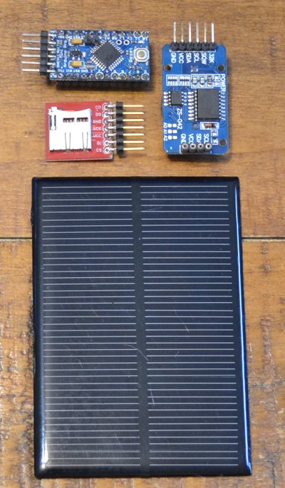
Mini Solar Panel
The mini solar panel I chose is one that seems hard to get these days. It is an "8V x 100mA" unit. Really it is 7V @ 75mA, but it will be plenty for this application. If you wind up building something like this, and you can't find one of these, any panel with a real voltage of 7V or more with a real current about 50 - 75mA will work fine. Even a 12V panel will work. The charger circuit will handle the over-voltage, so it is just the current you need to worry about. It needs enough current to charge the battery within the time calculated. You can wire them in series if you need to increase the voltage. Two 5V 50mA panels in series will generate 10V 50mA.
Battery
The battery should be sized to at least the total requirement of 32.4mAH so it can run for the three days (1 sunny and 2 cloudy). A single AAA battery with 240 to 300mAH should work fine. I started with a pair of 600mAH AAA batteries, but traded them for a single AA-sized 1200mAH lithium-ion battery. Over-spec'd, but it's what I have, and it doesn't hurt to have a little more battery than needed. I have a single-cell AAA battery holder on order and will try that out when it arrives.
MicroSD Card
The µSD card reader is just a socket, with no electronics on it at all. It has a straight SPI interface to the µSD card. I'm using a 256MB card in the hope that it uses less power than a larger card. Pins D10 - D13 are used to talk SPI to the µSD card.
RTC Module
The RTC is a module with a DS3231SN and a 24C32 EEPROM chip. It has had the power LED, all pullup resistors, and the "charging" resistor removed. If you get one of these things, remove the resistor right next to the pin "SCL". It puts Vcc on the battery, which is either A) not rechargeable and will explode, or B) rechargeable and will explode due to constant trickle charging. My CR2032 battery was quite swollen from a week of use. The code supports a DS1307 as well. The RTC is the trigger that wakes the CPU every second. The squarewave output is connected to the INT0 pin (pin 2). A4 and A5 are used as I2C lines to talk to the RTC.
Voltage Dividers
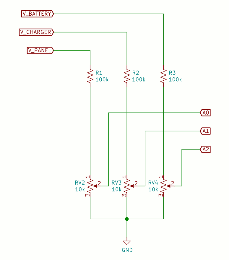
Don't connect the analog inputs to the dividers until you have calibrated them. You could destroy the MCU.
The voltage dividers used for measuring the three voltages are the same as the Uno solar project, but with higher resistance values to use less current. They are calibrated to read the same voltage as my best meter. The resolution is 14.5mV or so per ADU, so not too fine a reading.
To calibrate: Put a voltage of 9V - 12V on the top of the divider and use your calculator:
Top voltage ÷ 13.636363 = wiper voltage
Just adjust the pot until you get the calculated wiper voltage on the wiper. It will be less than 1.1V.
Then you can safely hook the wiper to the analog input.
Indicator
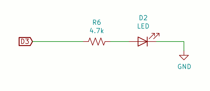
There is an LED with a 4.7k limiting resistor that signals the passing of the minutes by coming on for one second (second 59). The LED takes 190µA. It is the only way to tell the circuit is working.
Charger

The charger is an LM317T voltage regulator, set to 4.2V, and controlled by a 2N3904 transistor. When the transistor is off, the voltage on the output of the charger is 4.2V. When the transistor is on, the voltage becomes 1.25V at the output. A blocking diode prevents the battery from discharging into the regulator when the regulator is disabled or the sun sets.
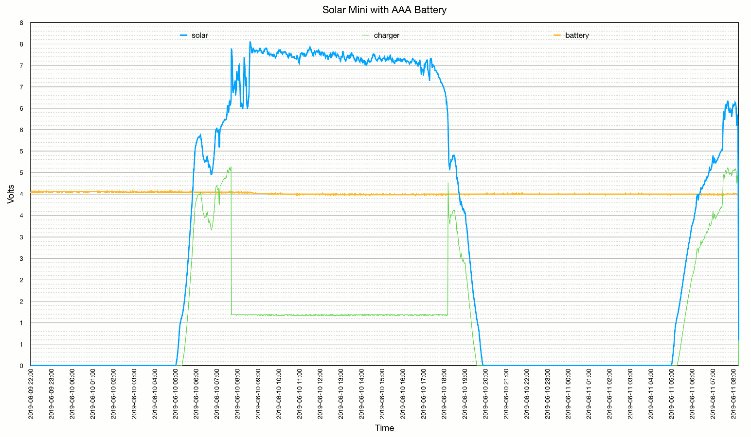
If the battery demands more current than the panel can produce, the panel voltage drops. When it drops below 1.5V + one diode drop (0.75V) above the battery voltage, the current will decrease. The solar voltage should hover at 2.25V above the battery until the battery is charged and the charger is shut down by the Arduino. You can see this happening in the output graph below (between 8:30 and 9:00 AM).
When the battery voltage gets above the "MAX_BATTERY" level, the transistor is turned on, the regulator drops its output, and charging stops. When the battery voltage drops to below the "MIN_BATTERY" level, the transistor is turned off and charging resumes. Both values are configurable in the code. There is also a minimum voltage on the solar panel that will allow charging, also configurable.
Performance

The blue line is the solar panel voltage, the green line is the charger voltage, and the yellow line is the battery voltage. The circuit doesn't drain the battery enough to need charging except in the early morning. It makes me wonder how many days it can go without running the battery to below 3.4V.
I had a chance to run it for a couple of days with a single AAA battery, and I'm happy to report that it works just as well as a larger capacity AA battery. I think the circuit draws so little current that it isn't much different to the battery than sitting on the shelf. Just doing some simplistic arithmetic on it suggests the 600mAH AAA battery might last nearly two months before going completely dead. A little more simplistic math says that to recharge it from the edge of death in one 5.14 hour day would require a little over 104mA of charging current.
Finally
Referring again to the Solar Powered Arduino Uno article, the mini performs magnitudes better than the Arduino Uno as a solar powered device. The relative cost of the solar panels ($8 vs. $26) is enough to justify using the $11 Arduino Pro Mini instead of the $24 Uno. Going from two large panels to one panel about half the size is a great savings of space, as well. The mini is exactly as capable as the Uno in remote applications, and is much smaller.