Arduino Solar Panel Project
This point of this project is to determine the appropriate mini solar panel to run an Arduino Uno during the day, and charge a battery enough to run it overnight. To do that we need to know how much power is needed, and how much power is available. I have a mini solar panel I like for this, but need to know how many I need, and what size and number of batteries are required.
Uno Voltage and Current Requirements
Current requirement for the Arduino Uno is around 54mA when it is running an app from the DC power source. More or less, of course, depending on the types of internal peripherals being used, and the I/O pin load. With some power saving tricks the current required to drive the Uno (with RTC and µSD card) can be reduced to around 28.5mA. When this project is first powered on, or is reset, it draws just over 50mA, but after one minute it drops to 28.5mA.
The input voltage is stated as 7V to 12V, and they mean it. In practice, anything below 7V will cause the voltage regulator to dropout. The range of voltages on a pair of series connected lithium-ion batteries is 6.0V at discharged to 8.4 at fully charged. The battery pack will go below 6V, and that is a problem. It probably will not come back from 4V or less. At our rate of consumption, the battery pack has used 60% of its capacity before the voltage drops to 7.4V, which is the voltage many people say is fully charged. At 7.0V the battery has less than 5% of its capacity left. The key to getting through the night seems to be getting enough batteries charged to 8.4V.
Availability of Sunlight
To charge the batteries we need sunlight. We'll design for the shortest day at +40°, which is around 9.17 hours from sunrise to sunset on December 21st [1].
If every day was a sunny day... [2] In the sunny southwest, they have 200+ sunny days, while in the Pacific northwest the number is more like 70. Also interesting from that source page is the "% Sun", which describes the effective daylight hours (the percent of sunlight actually reaching our panel due to clouds, etc.). Let's assume we're building this for a location in Louisville. Only 56% of our 9.17 hours are useful, which cuts our sun time to 9.17 x 0.56 = 5.14 hours per day.
Some Arithmetic
Since we will need 28.5mA x 24 hours = 684mAH per day, and we only generate electricity for 5.14 hours per day, we will need to generate 684mAH ÷ 5.14hr = 133mA for the duration of our usable daylight hours. 104.5mA goes to the batteries and 28.5mA to the Arduino.
The remainder of the day we run on batteries. That's 24 - 5.14 = 18.86 hours. If we design for this, we will probably fail at some point. Some days get very little sunlight. We need 684mAH to make it through the average day. If there are 2 cloudy days in a row, and we need 684mAH for each of those days, we need 1368mAH in storage.
Now that we have increased the number of hours we might operate on batteries, we need to determine a new charging current to get them recharged in, say, 2 days. 1368mAH ÷ (5.14 hours x 2 days) = 133mA. Add to that the regular load of 133mA, and we know we may be asked to deliver 266mA from the panel(s) during daylight hours.
You may notice that the discussion doesn't really include the panel voltage. That's because it doesn't matter, as long as it's high enough to charge the batteries with the current that was calculated.
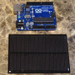
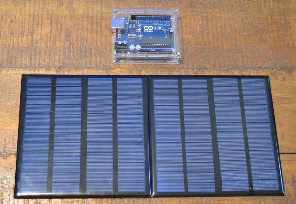
The Mini Solar Panel
The solar panels need to generate 266mA on average during the daylight hours, but the one I chose, a 12V 3W panel, only generates about 210mA max in the usable voltage range, so two need to be paralleled, which yields 420mA, which is well over the current required for that winter day in Louisville.
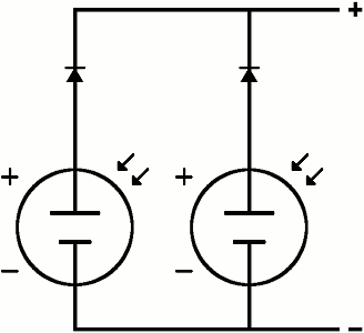
The two panels are wired up in parallel with blocking diodes to keep the current from one panel from going into the other when they are unbalanced, like when a bird lands on one of them. In the diagram they are shown wired together with a single positive and a single negative lead going to the charger circuit. The charger is built so it can accept either one pair of wires or two pair.
NOTE:
The blocking diodes are required if you have more than one panel, or if you are running them into the battery directly.
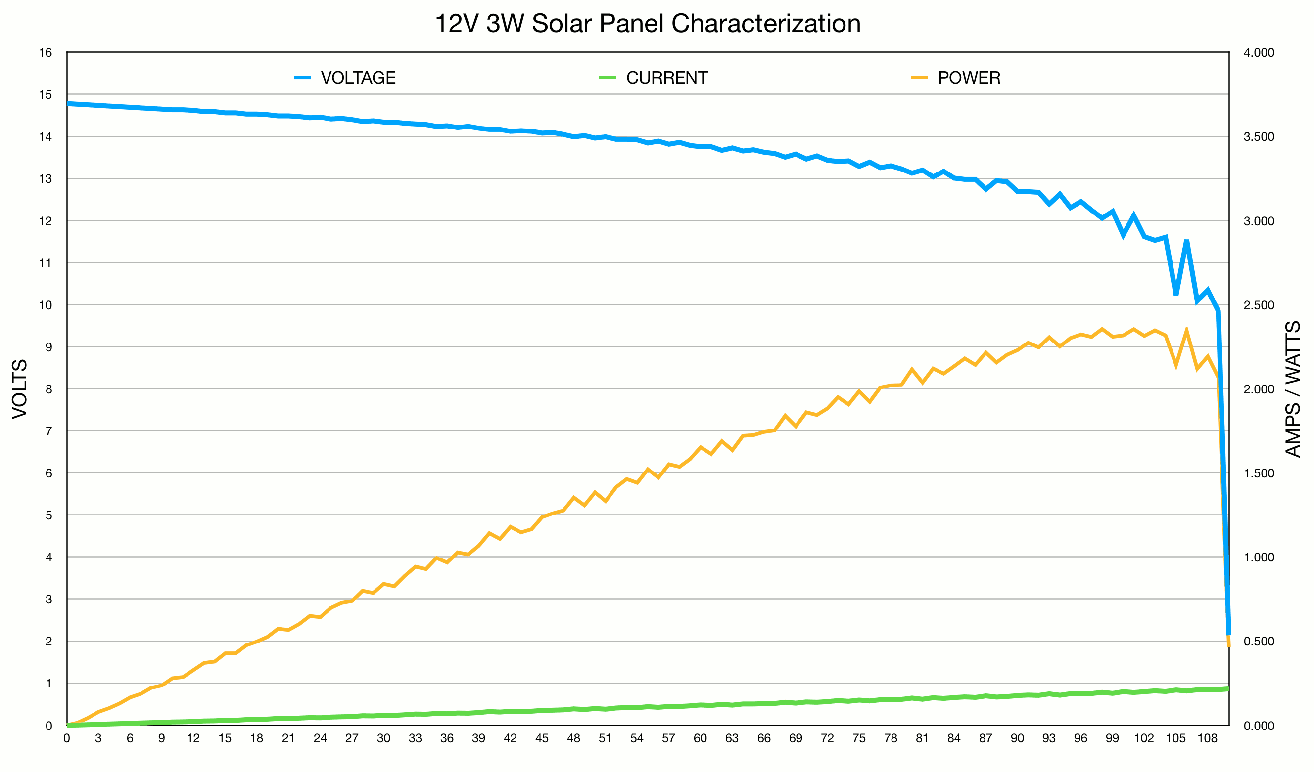
Each panel's output voltage ranges from 14.75V to 10.1V, depending on the load. They don't deliver a full 3W, peaking at 2.35W somewhere around 12.1V @ 195mA. The usable voltage is 0.7 to 0.8V lower due to the panels' blocking diodes. These 12V panels bring both good and bad. It is a good thing that the voltage is high enough to get a full charge. It is a bad thing that the voltage is way too high to directly drive the batteries without starting a fire.
Charger Circuit
To solve the high voltage problem I came up with a simple constant voltage charger. The current being put into these batteries never reaches the level of a constant current charge, but it isn't as low as a trickle charge, either, at (240mA - 28.5mA) ÷ 3 batteries = 70.5mA per battery. It isn't enough to cause worry about overheating the battery, and it is plenty to charge the batteries. It might be a problem if the charger didn't cut the current off at full charge.
There is a little twist with this circuit, due entirely to the fact that the battery voltage is too low to use a blocking diode in the line. The Arduino is always run from the battery. When the solar panels are connected, the batteries and the Arduino get their power from the panels. When they are disconnected by the charging circuit, the Arduino runs directly off of the battery - not the solar.
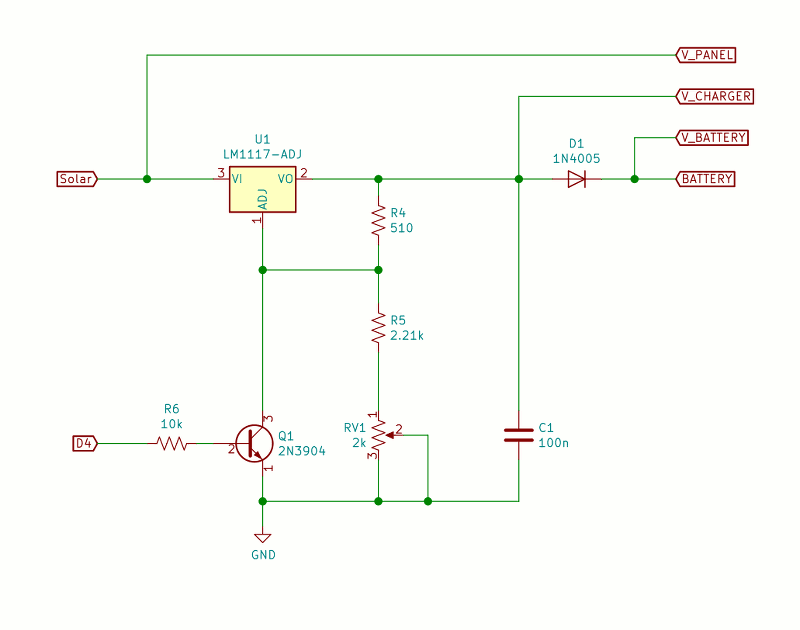
The charger schematic. It is just an adjustable voltage regulator that is set to 8.4V with batteries attached. The only unusual things are the addition of a blocking diode and a transistor switch that is controlled by the Arduino. When the battery is fully charged, the Arduino turns the transistor on, dropping the regulator's output to around 1.3V and stopping the charging process. The blocking diode prevents the batteries from discharging back through the voltage regulator. The Arduino can tell when the batteries are charged by shutting down the regulator and measuring the battery voltage. If the battery is above 8.35V, it is considered fully charged for this application.
The battery check is performed once per minute. If the solar panel is not generating a voltage greater than the battery voltage, shutdown will not be asserted. If the solar panel is generating more than the battery voltage, and the battery is not charged, shutdown will not be asserted. If the solar panel voltage is higher than the battery, but the battery is charged, shutdown will be asserted and the solar panels will not be charging the batteries.
If you can't find these particular panels, any 12V panels can be paralleled (with diodes) to get the current over 337mA. There are some nice solar panels on ebay, although I used this larger panel from Amazon.
Many panels are rated in Maximum Power Voltage (MPV) and Maximum Power Current (MPA), which define the MPP, and the real performance of the panel. An example is the 12V panel used here that is rated 12V @3W. It ranges from 14.8V to 10V, but is 12.1V at the MPP.
Lithium Ion Batteries
The number of batteries is determined by adding all of the capacities together. 684mAH for today and 1368mAH for the next two days is 2052mAH. Just paralleling two 8.4V 1200mAH packs might work, but it is cutting it close. Three would be wise.
I put 1200mAH AA-sized batteries in three battery holders that each hold two batteries in series to increase the voltage from 4.2V to 8.4V. Those battery holders were then wired in parallel to increase the capacity from 1200mAH to 3600mAH. Buy good batteries. All batteries must be the same brand, model, capacity, age, and have the same charge level.
The Measurement Circuit
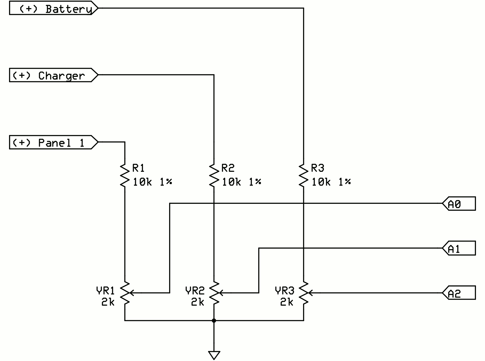
The ADC reference had to change from the 5V supply to the internal 1.1V reference because the 5V wasn't 5V, it was 5.13V, throwing all of the readings off. I added three dividers, each having a 10kΩ resistor and a 2kΩ trimmer pot. The pot was adjusted to make the reading from the ADC match the reading on a digital meter.
The solar panel, charger, and battery voltages are sensed by the three resistor dividers. They cut the max voltage from 15V down to 1.1V, and feed it to the analog inputs A0, A1 and A2. Each ADU is worth 1.074mV, but we divided the battery and panel voltage by 13.6363 using the resistors, so each ADU is worth 14.645mV at the battery or solar panel. We need to know this for the code that reads the analog inputs and converts them to a voltage value. The 8.4V signal works out to be about 574 ADU. 14.645mV x 574 ADU = 8.406V.
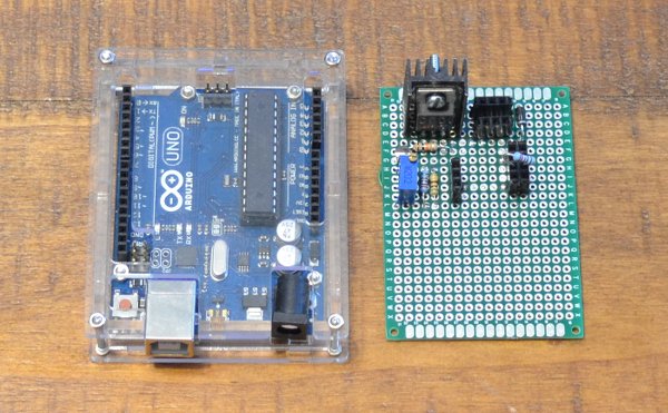
For the logger part, I used an I2C DS3231 Realtime Clock module and an SPI µSD card module. The clock is for time-stamping the data that is written to the µSD card once every minute. The data is appended to a CSV file, which when read into a spreadsheet program, may be used to make some interesting plots. The clock, being low power, has an LED marked "Power", which uses more power than the RTC itself. That needs to be removed, as does the power LED on the Arduino Uno. I used a cheap clone for this. I'm not going to wreck a $25 Arduino Uno.
Power Savings
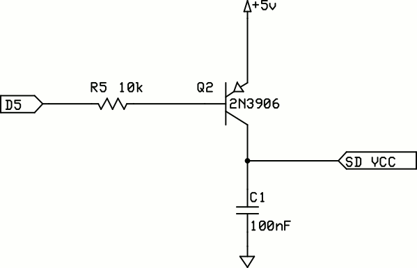
The Arduino Uno has an ATmega328P microcontroller. The "P" is the important part. It means it has enhanced power control. You can put it to sleep and wake it when something important happens, like the constant pulsing of the 1Hz squarewave output of the RTC. The sleep mode cuts power considerably. This is such a power hungry circuit to start with that I was only able to get the power down to 28.5mA. Some of the power is the µSD board with its regulator and the µSD card itself. I added a PNP transistor to cut the power to the µSD board and only bring it up a few milliseconds or so before it is needed. That dropped 4mA from the total current.
How about a Solar Powered 3.3V Arduino Pro Mini?
I used this method to determine power requirements on a logger project and using the 3.3V Arduino Pro Mini and it was able to run with a single 1200mAH Lithium Ion battery and a single 7V solar panel about 100mm x 69mm.
The Arduino Uno has an always-on LED, two regulators, and two MCUs on the board. The Mini has one regulator, one MCU, and one LED that is constantly on. If your Pro Mini has a power LED, you can easily take it off. You can get average power consumption to below 500µA @3.3V with an RTC and an SD card.
See the Arduino Pro Mini 3.3V solar tutorial for a practical example.
Indicator
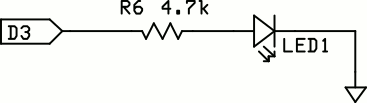
I added an LED (named INDICATOR) with a 4.7k resistor to indicate when the 0th second comes. It is the only way to verify the circuit is working, short of pulling the µSD card and reading it. The LED is on for all of second 59. It uses around 400µA while it is on. The Arduino's "L" LED is on pin 13, which is also used for the µSD card, so it flashes dimly when the µSD is being written, but that doesn't add up to much total current.
Code
This is the code to run the Solar Uno test. The timer0 interrupts are disabled so the CPU won't be awakened 1000 times per second. The CPU is put to sleep, then awakened by the 1Hz interrupt from the RTC every second. It looks to see which second it is, and if it is second 59, it stays awake long enough to read the RTC to get the real second. If the RTC second is zero, the ADC inputs are read and used to calculate the three voltages. The result is written to the SD card as a line in a CSV file. The seconds counter is reset to zero and the CPU is put to sleep again. The reason for the run around on the seconds is there can be spurious interrupts (like lightning 20 miles away) that cause false increments of the seconds counter and the way it is written guarantees the ticker will sync up within one minute.
// The timer0 interrupt is disabled, so the delay()
// functions will not work. Use _delay_ms() instead.
#include <SPI.h>
#include <SD.h>
#include <Wire.h>
#include <avr/sleep.h>
#include <util/delay.h>
#include "RTClib.h"

#define DS_3231
//#define DS_1307

#ifdef DS_3231
RTC_DS3231 rtc;
#else
RTC_DS1307 rtc;
#endif

#define V_PANEL A0
#define V_CHARGER A1
#define V_BATTERY A2

// Blips for one second every minute.
#define INDICATOR 3

// Shuts down the charging circuit.
#define SHUTDOWN  4

// Turns on the SD card supply.
#define SD_POWER 5

// This is the mV at the battery/panel for one ADU:
// (15v / 1.1v) * (1.1v / 1024)
// 13.636363 * 0.00107421875
#define ADC_FACTOR (double)0.0146484375

// Change the chipSelect to match the CS you choose on
// your SD card module.
#define chipSelect 10

int ticker = 0;
char buf[40];
char tmpBuf[8];
double v_panel, v_charger, v_battery;
DateTime now;
char filename[] = {"solar.csv"};

/*****************************************************************************
 * isShutdown
 *
 * Reports on the state of the SHUTDOWN bit.
 *****************************************************************************/

bool isShutdown() {
  return digitalRead(SHUTDOWN)?true:false;
}

/*****************************************************************************
 * getSolarVoltage
 *
 * Returns the voltage on the solar panel.
 *****************************************************************************/

double getSolarVoltage() {
  return analogRead(V_PANEL) * ADC_FACTOR;
}

/*****************************************************************************
 * getChargerVoltage
 *
 * Returns the voltage on the charger output.
 *****************************************************************************/

double getChargerVoltage() {
  return analogRead(V_CHARGER) * ADC_FACTOR;
}

/*****************************************************************************
 * getBatteryVoltage
 *
 * Returns the voltage on the battery bus.
 *****************************************************************************/

double getBatteryVoltage() {
  return analogRead(V_BATTERY) * ADC_FACTOR;
}

/*****************************************************************************
 * saveReadings
 *
 * Reads the voltages off the analog pins and writes
 * them as a line in a CSV file on the SD card.
 *****************************************************************************/

void saveReadings() {

  digitalWrite(SD_POWER, LOW);

  if (!SD.begin(chipSelect)) {
    Serial.println("SD Card failure");
  }
  memset(buf, 0, sizeof(buf));
  sprintf(buf, "%4d-%02d-%02d %02d:%02d,",
    now.year(),
    now.month(),
    now.day(),
    now.hour(),
    now.minute()
  );
  // Read the panel voltage.
  v_panel = getSolarVoltage();

  // Read the battery voltage.
  v_battery = getBatteryVoltage();

  // Read the charger voltage.
  v_charger = getChargerVoltage();

  // Some icky string formatting.
  memset(tmpBuf, 0, sizeof(tmpBuf));
  dtostrf(v_panel, 6, 3, tmpBuf);
  strcat(buf, tmpBuf);
  strcat(buf, ",");

  memset(tmpBuf, 0, sizeof(tmpBuf));
  dtostrf(v_charger, 6, 3, tmpBuf);
  strcat(buf, tmpBuf);
  strcat(buf, ",");

  memset(tmpBuf, 0, sizeof(tmpBuf));
  dtostrf(v_battery, 6, 3, tmpBuf);
  strcat(buf, tmpBuf);
  strcat(buf, "\\n");
  Serial.print(buf);

  File dataFile = SD.open(filename, FILE_WRITE);

  if (dataFile) {
    dataFile.print(buf);
    dataFile.close();
  } else {
    Serial.println("error opening " + (const)filename);
  }
  digitalWrite(SD_POWER, HIGH);
}

/*****************************************************************************
 * setCharger
 *
 * Determines the correct state of the charging switch
 * based on the solar, charger, and battery voltages.
 *****************************************************************************/

void setCharger() {

  // Power supply maintenance.
  if (isShutdown()) {
    // The charger is shutdown. Just check the voltage and see
    // if it is lower than we want it to be.

    // Only charge if the sun is up.
    if (getSolarVoltage() > 9.0) {
      if (v_battery < 8.29) {
        // Turn the charger back on.
        digitalWrite(SHUTDOWN, LOW);
      }
    } else {
      // Save a milliamp and turn off the shutdown transistor.
      digitalWrite(SHUTDOWN, LOW);
    }
  } else {

    // If the sun is up...
    if (getSolarVoltage() > 9.0) {

      // Shutdown the charger.
      digitalWrite(SHUTDOWN, HIGH);
      _delay_ms(250);

      // See if battery is charged.
      if (getBatteryVoltage() < 8.35) {
        // Not charged - don't leave it shut down.
        digitalWrite(SHUTDOWN, LOW);
      }
    }
  }
}

/*****************************************************************************
 * setup
 *
 * Initializes everything.
 *****************************************************************************/

void setup() {
  // Open serial port
  Serial.begin(115200);

  pinMode(INDICATOR, OUTPUT);
  digitalWrite(INDICATOR, LOW);

  pinMode(SHUTDOWN, OUTPUT);
  digitalWrite(SHUTDOWN, LOW);

  pinMode(SD_POWER, OUTPUT);
  digitalWrite(SD_POWER, LOW);

  pinMode(chipSelect, OUTPUT);

  // See if the SD card is present
  Serial.println("Check SD card");
  if (!SD.begin(chipSelect)) {
    Serial.println("SD Card failed, or not present");
    while (1);
  }
  Serial.println("SD Ok");

  // See if the RTC is present
  Serial.println("Check RTC");
  if (! rtc.begin()) {
    Serial.println("No response from RTC");
    while (1);
  }
  Serial.println("RTC Ok");

#ifdef DS_3231
  if (rtc.lostPower()) {
#else
  if (!rtc.isrunning()) {
#endif
    Serial.println("Set RTC time");
    rtc.adjust(DateTime(F(__DATE__), F(__TIME__)));
  }
#ifdef DS_3231
  rtc.writeSqwPinMode(DS3231_SquareWave1Hz);
#else
  rtc.writeSqwPinMode(SquareWave1HZ);
#endif

  now = rtc.now();
  ticker = now.second();
  Serial.print("Second: ");
  Serial.println(ticker);

  // Disable timer0
  TIMSK0 &= ~_BV(TOIE0);

  // Enable the interrupt as a falling edge.
  attachInterrupt(digitalPinToInterrupt(2), Int0, FALLING);

  // Change the referenceto the 1.1V internal because the
  // 5V regulator on my board puts out 5.13V.
  analogReference(INTERNAL);

  // Clear out one read.
  analogRead(V_PANEL);

  // _delay_ms() to allow chrs to xmit before
  // MCU goes to sleep.
  _delay_ms(10);
}

/*****************************************************************************
 * loop
 *
 * Main program loop
 *****************************************************************************/

void loop() {

  // Go to sleep until interrupted.
  set_sleep_mode(SLEEP_MODE_PWR_DOWN);
  sleep_enable();

  // Must enable or can't wake!
  sei();
  sleep_cpu();

  // Zzz...Until Int0 fires.

  sleep_disable();

  // Just skip 58 seconds, but after that, read
  // the RTC to get the real second.
  if (++ticker > 58) {
    digitalWrite(INDICATOR, HIGH);
    now = rtc.now();
    if (now.second() == 0) {
      ticker = 0;
      digitalWrite(INDICATOR, LOW);

      // Save the voltage readings to SD card.
      saveReadings();

      // Set the charging state.
      setCharger();
    }
  }
}

// The Int0() just needs to be here - it doesn't have to do anything.
void Int0() {;}
The code may be modified to use either a DS1307 or a DS3231 RTC module, thanks to the Adafruit RTC library, which makes them look nearly the same. There is one line that needs to be changed from DS_3231 to DS_1307.
The text below is that sent to the serial port. It starts with the checks, adds a line to tell you what second the RTC is on (so you know how long before the first reading), and then echoes the data written to the SD card. One line per minute.
SD Ok
Check RTC
RTC Ok
Second: 33
2019-06-01 08:14,10.269, 8.730, 7.939
2019-06-01 08:15,10.283, 8.745, 7.939
2019-06-01 08:16,10.283, 8.730, 7.939
2019-06-01 08:17,10.283, 8.745, 7.939
2019-06-01 08:18,10.283, 8.730, 7.939
2019-06-01 08:19,10.298, 8.730, 7.939
2019-06-01 08:20,10.327, 8.760, 7.954
2019-06-01 08:21,10.386, 8.804, 7.954
2019-06-01 08:22,10.415, 8.818, 7.969
2019-06-01 08:23,10.415, 8.818, 7.969
2019-06-01 08:24,10.459, 8.848, 7.983
The whole thing - breadboard, batteries, and solar panels - was placed outside to run for a day or so to see what happened. The results are the graphs seen below.

This graph shows about 3 hours of operation as a sort of close up view of the charger operation. The charger is bumping the battery charge up every 15 to 30 minutes.
The blue line is the solar panel voltage. The yellow line is the battery voltage. You can see that the battery voltage is maintained through the day after it reaches a full charge. The green line is the charger output. It stays high while the batteries are charging, then drops to stop the charging when the batteries have a full charge (8.35V). The charger will come on and top off the batteries if they drop below 8.29V.
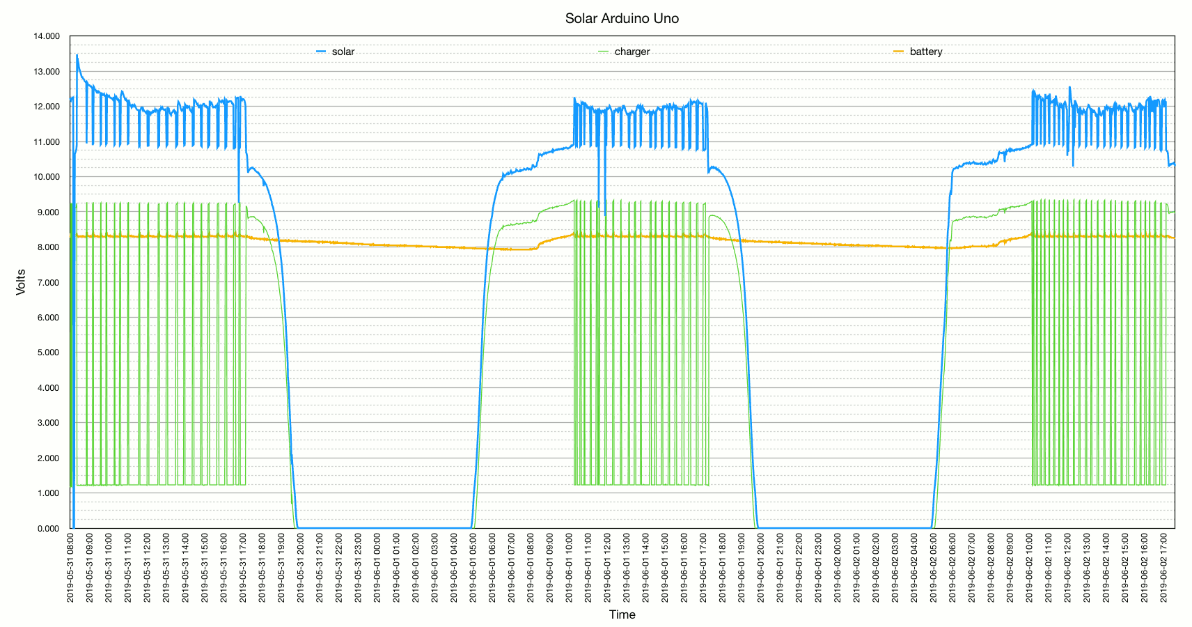
One of the most important takeaways from this graph is the recovery time of the batteries, which was right at 2 hours of continuous charging to completely recharge them - the benefit of having a larger than needed solar panel. It ran about 15 hours without charging. The voltage only dropped 0.425V during that time, and would indicate that the batteries were not anywhere near halfway discharged. The calculated discharge was 427.5mAH (15h x 28.5mA). The batteries are supposed to be 99% efficient, so the 2hrs of charging would have been at an average of 244mA (427.5mAH for the battery + 57mAH Arduino during recharging) ÷ 2hours ÷ 0.99). More or less. The battery charged at (244mA - 28.5mA) ÷ 3 = 71.83mA per battery. In the shortest day after two relatively poor days scenario, a single solar panel would have required (427.5mAH x 3 days) / (203mA - 28.5mA) = 7.3 hours charging time, assuming all available current from the panel could have been used, and that time was just not available. It would have required at least two days to charge the batteries, which was within our design specs, but uncomfortably near the edge.
I'm going to call it a successful experiment, in that I learned a good way to estimate solar panel and battery size. It also proved the benefit of using power control techniques to reduce consumption, without which the whole system would have been twice the size, and twice the cost. It is very possible to power an Arduino Uno using solar power and batteries, without straying into design absurdity. It is a reasonable design, albeit not ideal.