DIY ATmega Dev Board
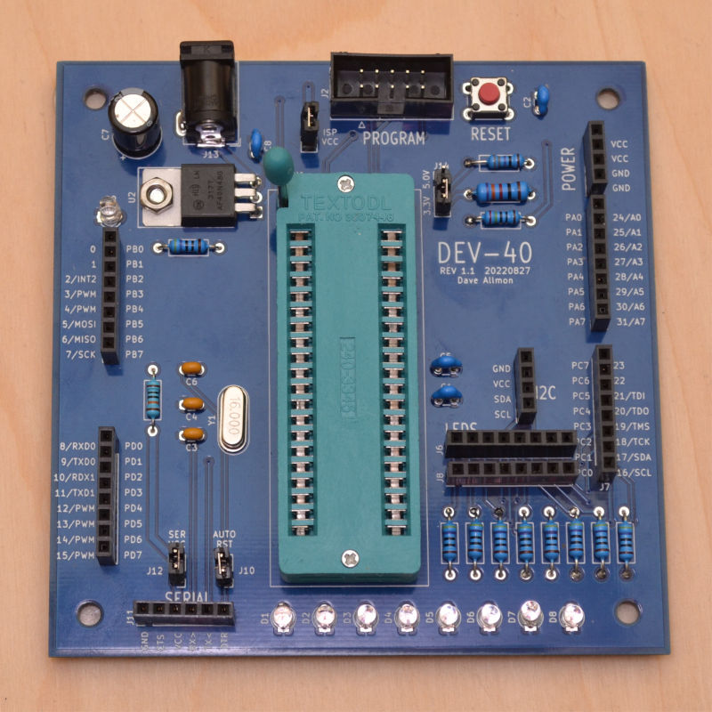
This project actually started years back. I built a couple of boards - one for the ATmega328, etc., and one for the ATmega1284, etc. They were very well received, but there was a small problem: the PC boards cost $85 for 3 boards. And what's more, they were only 2.5" x 3.8" due to a restriction at the PC board house. I still have one, and use it regularly. So why build this one? There are features on the old board that I never use - pots and push-button switches. There are features missing on the old board. Power pins and 8 LEDs, so I can monitor an entire port. And the fact that I can either monitor the pin or use the pin for something useful - not both. It has a regular DIP socket, instead of a ZIF socket. I hope this new board has a more usable feature set.
NOTE: The pinout of port A has changed since the pictures were taken. The connector has been reversed so that all 32 digital pin numbers are in order going counter-clockwise around the board. The KiCAD project files and the interactive BOM reflect that change.
Features
Use and monitor a pin at the same time. There are two parallel pin sockets for each LED, so I can run a wire from the port to the LED, then from the LED to the workload.
View an entire port at one time. There are 8 LEDs on the board now, with resistors chosen to let the LED work at both 5V and 3.3V.
The voltage regulator is jumper programmable for 5V or 3.3V VCC. I used an LM317 and a parallel resistor to drop the regulator output from 5V to 3.3V when a jumper is installed.
More flexibility in power sources. The board may be powered from a 9 to 12VDC wall wart, the ICSP port, or the serial port. One at a time, please. Jumper selectable.
There are 4 power supply output header pins. 2 pins for VCC, and 2 ground.
The board has enough space to label everything. The pins are labeled with digital pin (0 - 31), analog pin (A0-A7), alternate use (SDA, RXD1, etc.), and port pin (PA0-PD7). There are so many alternate uses that there wasn't room for them all. The board is also, at 100mm square, more stable than the old ones.
The MCU socket is a ZIF socket. Because there is more room, I could use the ZIF socket. Handy, since the use of the board is to develop a project, then move the MCU to a dedicated board.
There is a dedicated I2C port. I put a 4-pin port on the board that supports I2C, using the closest thing I could find to a standard pinout. It seems to match more than one display, anyway. Be aware that it uses whatever is programmed for VCC, so It could be 5V, or it could be 3.3V, depending on the jumper. The I2C devices will not like a different VCC than they are designed to use.
All pins are brought out to headers. All 32 I/O pins are available on the headers, and some of those with double duty are brought out in 2 places. The I2C port above is an example, as is the 6-pin serial port with the FTDI compatible pinout. Choose a male or female header for the serial port to match your serial device. Since they all seem to come with a male on the end, I chose a female header for mine.
Jumper programmable Auto Reset. For uploading code, if a bootloader is installed, you can set it to automatically reset the MCU to put it into programming mode. I don't often use a bootloader, because they delay the start of my code, and in many applications, that is a bad thing.
No SMD. Everything is though-hole, so it can be assembled with just a soldering iron.

The schematic calls out an ATmega1284, but it is compatible with:
- ATmega16
- ATmega32
- ATmega164
- ATmega324
- ATmega644
- ATmega1284
- ATmega8535
The port use varies between models, so some labels may not be perfect for some MCUs. For example, some chips don't have a second hardware serial port. All the digital and analog pin numbers, and the port pins are the same between parts.
PC Board
The prototype PC board came from PCBWay.com. If you don't have a lot to spend on a PC board, but you still need a quality board, I can recommend PCBWay. The quality of these boards is great. They charge as little as $5 for 10 prototype boards, have all the options you could want, and make it in anywhere from 2 to 4 days. They're pretty good at estimating the time requirement, and you can follow your boards through the manufacturing process to see where they are at any time. They even have videos of most steps, so you can see what each station does. Really fascinating.
I discovered an interesting thing recently. KiCAD takes plugins. It ships with them, at least when you install KiCAD on Ubuntu using the Software Center. One of the plugins is a PCBWay plugin. I tested it. When you are done with the design, you click the "PCBWay" button, and it zips your files, sends them to PCBWay.com, and fills in all the quotation fields, except the number of boards. You have to do that. Of course, if you want anything other than the default options, you will want to change them. But it really makes ordering the boards easy. Very slick.
Other parts came from Mouser, Microchip Direct, ebay, Amazon and AliExpress.
Assembly
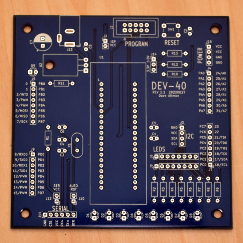
Another interesting KiCAD plugin is the Interactivee BOM plugin. See what it does below.
Interactive BOM/Placement Diagram
Refer to the parts list and layout to place the components. Notice the crystal is listed in the parts list as 16MHz. You might want to use that frequency, or you might not. If you leave the crystal off until you have MightyCore installed on your computer, you can be more informed on the frequencies MightyCore supports. One of them might be more appropriate for your use. You can use machine pin sockets to hold the crystal, so you can switch it whenever you want. You would cut the leads shorter than they come, so the crystal nearly rests on the sockets. But wait for that.
There is no trick to the assembly, but I usually place the parts based on their height from the board surface. I place a few resistors, flip the board over on a soft (silicone) flat surface and solder those parts, then repeat for the next batch. In general, I go in this order:
- Resistors
- Ceramic Caps
- Regulator, reset switch, and crystal
- LEDs
- Connectors and jumper pins
- Electrolytic caps
- ZIF socket
That's how I do it, but there is no right or wrong way.
When assembly is complete, and before installing the MCU, check the power supply voltage with the jumper on 5V and then with the jumper on 3.3V. If the 5V is way too high, like around 5.8V, you probably have the resistors R12 and R13 switched. The values of R12 and R13 are critical. They fall within the standard 1% range of values, though, so they're easy enough to get. If you don't care about 3.3V, you can leave R13 out and the voltage will be 5V regardless of the jumper position, or you could also leave the jumper out.
With the appropriate jumper, you can run the MCU power off of either the ICSP port or the serial port. "ISP VCC", near the ICSP header, enables power from the ICSP header. "SER VCC", near the serial header, enables power from the serial port. Don't jumper both, and don't jumper either with the wall wart plugged in. You could damage your computer through the USB cable(s). Keep in mind the voltage switch or jumper position on the programmer, and make it the same as the voltage you've selected for the project.
Using the Development Board
With the MightyCore bootloader and board support, the 40-pin ATmega will act just like an Arduino. You need a USBASP, or similar ICSP to program the bootloader and then a USB-to-serial converter to program it using the bootloader. To get MightyCore installed in the Arduino IDE, go to "Preferences" and add the following url to the "Additional Boards Manager URLs":
https://mcudude.github.io/MightyCore/package_MCUdude_MightyCore_index.json
Close and restart the Arduino IDE to reload the board data. Then open the Boards Manager under Tools->Board->Boards Manager and go to the bottom to install the MightyCore boards. The selection of boards will increase considerably to include all the ATmegaxx4 chips, ATmega16/32, and ATmega8535. Take a few minutes to familiarize yourself with the MightyCore options. You don't have to use a bootloader - you can use the USBASP to just burn the code into the chip, and save room and save time on boot. Hold down the shift key as you click on the program button to flash the code.
If you want to program the device using a serial upload, you'll need to burn the bootloader first. To do that, on the Tools menu, set the board to MightyCore->ATmega1284 or whatever your device is, select the variant (in my case "1284"), bootloader "Yes, UART0", and the pinout, which is "Standard". Then on the same tools menu, select the ICSP programmer you are using, and then finally, select "Burn Bootloader". The Arduino IDE will burn the appropriate bootloader into your chip, and you're ready to go.
If you've made it this far, you now have a 40-pin Arduino. Most of the example sketches will run. For the "blink" sketch, or any sketch that uses the LED pin, you'll need to run a wire from digital pin 13 to one of the LEDs. You can burn the sketch by uploading through the serial port (by clicking the "Upload" button), or burn it using the ICSP port (by holding "SHIFT" and clicking "Upload").