DIY HiFi System

There are no affiliate links on this page. The links are all just links.
In early 2013 I decided to build a pair of speakers. They were open baffle panels with six 8" woofers and two tweeters per panel. They sounded great, but my wife took one look and said "Not in my front room." Ok. Plan B.
I redesigned them a couple of times and wound up with a pair of speakers that were 71/2" wide by 18" deep by 36" tall. They were running on two Sure 4-channel 100W Class D amplifiers. 800 watts of digital "sandpaper for your ears". With 1% distortion at 64W and 10% at 100W. Listening for longer than 20 minutes at a time was difficult. I set out to find an analog replacement, but analog amplifiers can be expensive, and I needed 10 channels. One for each driver and two for the sub. I decided on something with the LM3886 in it. I could have built amp boards, and power supply boards, but I ran across an assembled stereo board with rectifier, filter capacitors and heatsink for only $38. I grabbed one for the subwoofer, and ran it for about a year while the mains were running on the digital amps.
This post is about turning that amplifier and other components into a hifi system. The parts box already had the first stereo amplifier, and a pair of MiniDSPs running the 4-way crossover plugin. I already had the subwoofer with velocity feedback in operation. The Speakons were in the old amplifier case. The main speakers were built. The rest took some time to gather. I'd say about two years from the time I decided to do it until I had all of the parts.
"The Stack"
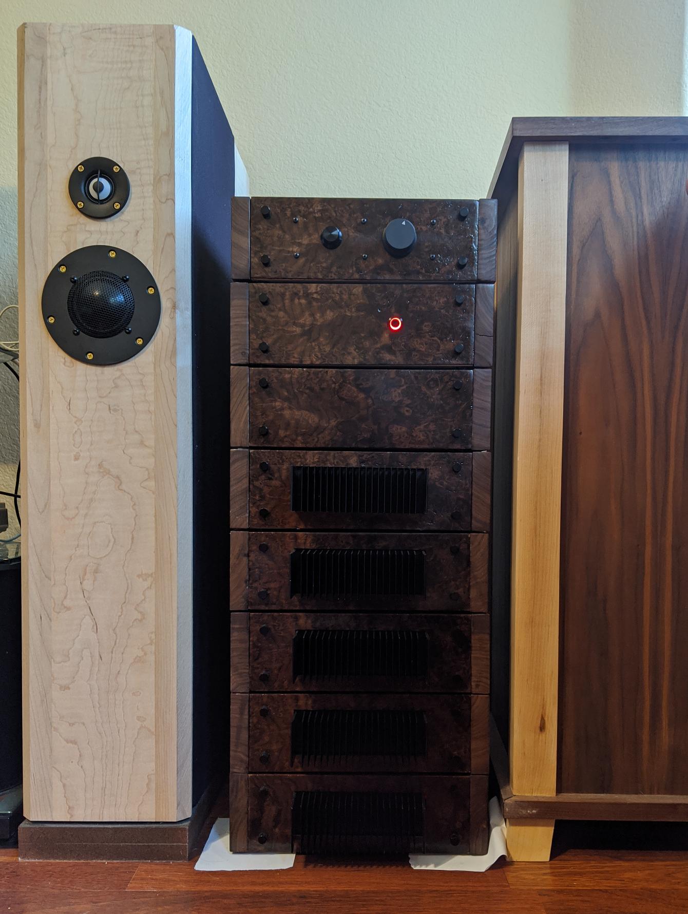
To the left is one speaker, to the right is the subwoofer. From the top down the boxes (and their approximate costs) are:
| Unit | Cost |
|---|---|
| Passive Preamp | $134.52 |
| Power Control Unit | $157.02 |
| Crossover | $221.52 |
| Tweeter amp | $126.24 |
| Midrange amp | $126.24 |
| Woofer #1 amp | $126.24 |
| Woofer #2 amp | $126.24 |
| Subwoofer amp | $177.02 |
| Total Cost | $1195.04 |
I put a large box in the garage, and as time passed, added things to it, starting with 4 amplifiers, then 4 transformers. An outline of the steps to build the system helped me think of parts that were missing and refine the build process. After the last part was purchased the building spree began, and following the outline, I built all of the units over the course of about three weeks.
Enclosures
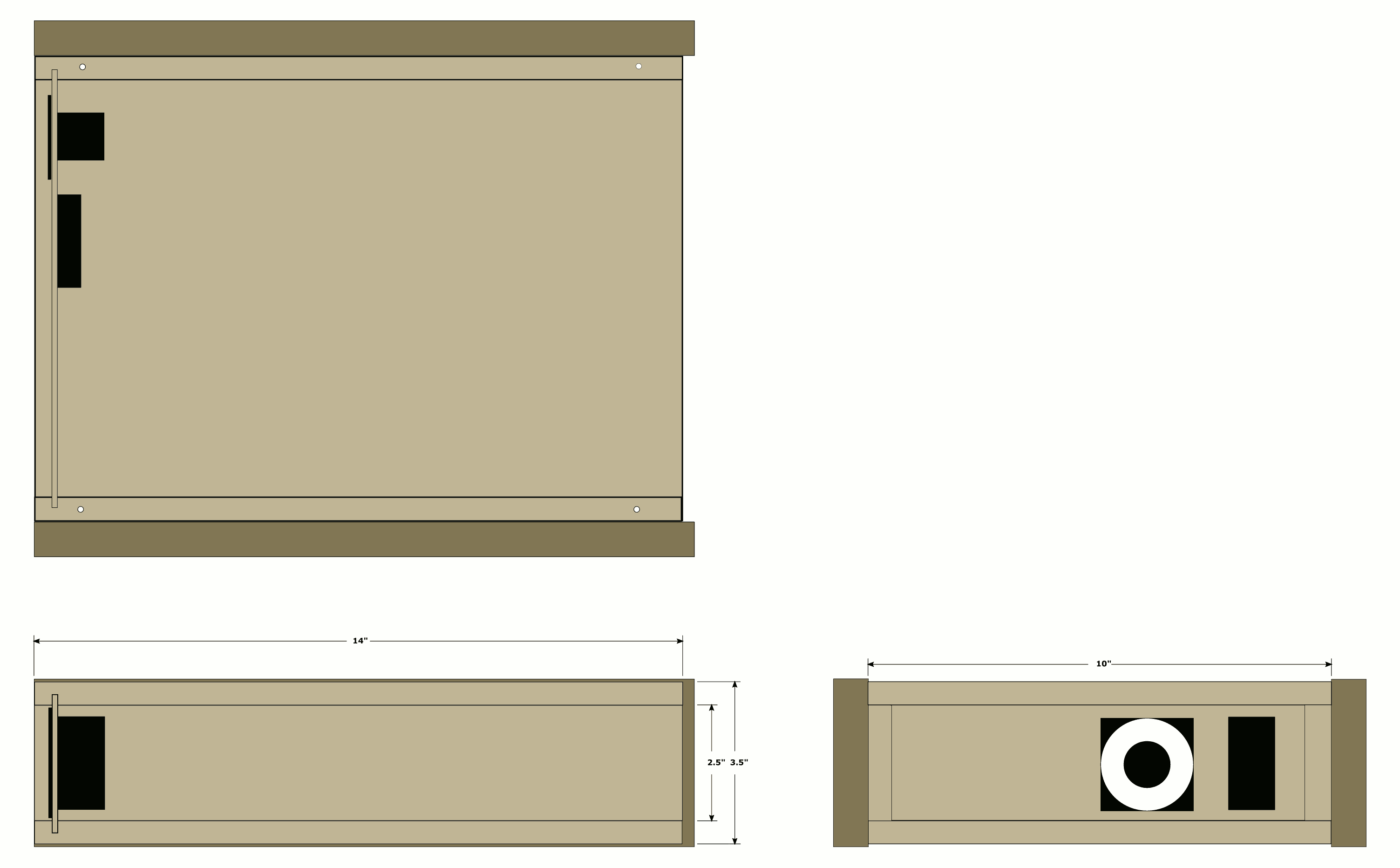
The boxes are each 111/2" wide by 141/4" deep by 35/8" high overall. The carcass is 12mm Baltic birch plywood. The front and rear panels are 3mm Baltic birch, with the front panels being veneered with walnut burl veneer. The side panels are 13/16" walnut. All but the preamp have fused IEC connectors and a 50mm fan. The box contributes $43.52 to each unit's cost. It includes the IEC, fan, feet, wood screws, thumb screws, PCB standoffs, finishing materials, etc.
I bought a 5 ft. by 5 ft. sheet of 12mm Baltic birch ply from Woodworkers' Source, which they cut into 8 ea. 15" x 30" pieces, and I trimmed to 14" x 30". I cut a groove slightly wider than the back panel thickness, 3/8" from one long edge on all pieces. Then cut them across in this order: 10", 10", 21/2", 21/2". Those are the parts for one box. One 14" x 30" piece makes one box. I cut all of the 10" widths first, then all of the 21/2" widths so I was sure they were all identical. The plywood was $36.00.
The side dress panels were made from "high character" walnut, meaning you have to work around knots, cracks, etc. The figure is great, but it was a lot of work. I cut them 35/8" x 141/4", then rounded over all of the edges except the back end using a router table and 1/8" roundover bit. Not considering waste, the boxes required a total of 5.75 board feet. I used 14 board feet. That means there were 8.25 board feet of waste. The high character walnut is not very good for making straight boards from. The walnut was $112.00 total.
The front panels were made from 21/2" x 12" x 3mm plywood. I added a 3/4" x 3mm strip of walnut to each long edge (the short edges will be hidden) and pressed walnut burl veneer on both sides. Then I cut to 31/2" width and 10" length by trimming half the waste off of each side/end. The walnut burl veneer was $60.00 total from veneersupplies.com. There is considerable waste, and you have to veneer both sides of the panels.
The front panels are held on using knurled 6-32 thumb screws like one would buy for their fancy computer case. There are PCB mounting angle brackets screwed to the inside of the side panels into which the thumb screws thread. Pan or truss head screws would have worked just fine, but the knurled screws look nicer. The thumb screws were $20 for 40 pieces, and I used 32. They were from Amazon.
All in all, the boxes cost $348.17. Of that, $192.00 was to make them pretty. That's $24.00 per box for form, and $20.00 for function.
Passive Preamp

After I picked up the CD player from Goodwill, and the DAC from Schiit, I realized that there was no way to turn the volume down. I had an extra box, Amazon had a switch, and Parts Express had a pot. I dug out my ebay 2-conductor shielded cable and built a passive preamp.
The preamp box is shielded with copper foil, which cost around $22.00 total, and is of dubious value. The switch is a ceramic rotary switch, 3 position (only 2 are used). They always have too much of a detent, so the spring that pushes against the detent had to be bent just a little so I could turn it with a small knob. The volume pot is an Alps 50k. That pot is so smooth. Beware of fakes. Get it from Parts Express, or somewhere else reputable. The fakes are far worse than any brand name pot, if the horror stories are to be believed.
As an aside, the gain matching turned out pretty good. The DAC max output is 2.0VRMS, which matches the MiniDSP's 2.0VRMS max input. The MiniDSP outputs 0.9VRMS max, and the amplifiers have a max input of 1.0VRMS.
There was a quiet buzz in the left midrange and tweeter that did not change with the volume setting. After the preamp was rewired with Mogami W2549 cable, the buzz is gone. It is impossible to say for sure it was the cable because I may have soldered better the second time around, but I think it was the cable. The clarity improved, too. All of the ebay cable is in the trash now.
Total cost was $134.52. The enclosure and the knobs were over half of the cost.
Power Control Unit
I needed a way to turn all of this on and off with a single power switch. That is all the power control unit does. It gets its power from the single power supply cord and distributes it via six pigtailed power cords.
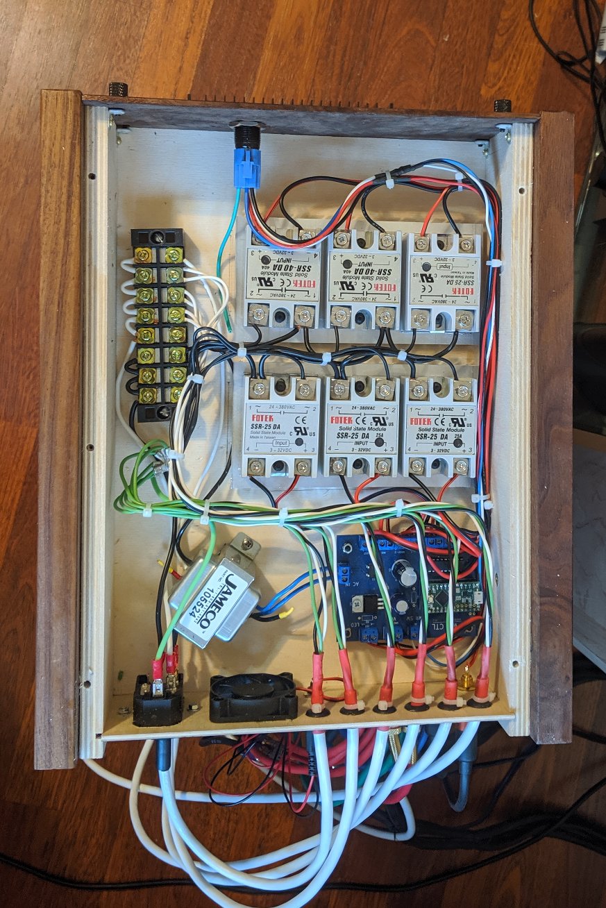
Six fake 25 or 40 amp Fotek SSRs from ebay stores switch the power. The SSRs are mounted on heatsinks. I had no way to determine the heat output of the fake SSRs, so I went with a nice 0.5" thick heatsink profile from heatsinkusa.com. There are two heatsinks, each carrying three SSRs. Holes beneath the heatsinks allow air to be drawn across the fins, which face downward. The fake SSR's are rated at 25A, but can't possibly handle that. They are adequate for switching the <2A load of the amplifiers, though.
The SSRs are controlled by a Teensy LC running Arduino code that turns on power to the units one at a time to limit inrush current. The Teensy also supplies the 0 - 3.3V voltage for the MiniDSP volume controls. The volume is set to zero on power up, then after the amps are all up and the protection relays have had time to close, the volume is ramped up to max. On power down, the volume is ramped to zero before the amps are powered down.
The rear panel has the IEC, fan and fan power, along with the six power outputs and the volume output to the crossover. The front panel has the power switch with internal LED. The cost was $157.02 for the PCU, mostly from the PCB (~$45), SSRs (~$30), and enclosure (~$43).
These files pertain to the blue PCB in the picture. It is the power control board, and runs everything on power up and power down. The board was designed in KiCAD.
The buttons below will show you the source for the Teensy program, or allow you to download it. It requires an Arduino environment with the Teensy board definitions added to it, and a Teensy LC board. The Teensy LC was chosen because it has a real DAC.
#define SSR_XOVER 2
#define SSR_SUB 3
#define SSR_WOOF_1 4
#define SSR_WOOF_2 5
#define SSR_MID 6
#define SSR_TWEET 7
#define PWR_LED 8

#define LED 13
#define POWER_SWITCH 14

#define VOLUME A12

#define SSR_ON 1
#define SSR_OFF 0

#define LED_ON 1
#define LED_OFF 0

#define PWR_LED_ON 1
#define PWR_LED_OFF 0

#define POWERED_ON 1
#define POWERED_OFF 0

#define INRUSH_DELAY 1500
#define SHUTDOWN_DELAY 500

#define VOL_RAMP_UP_DELAY 1
#define VOL_RAMP_DOWN_DELAY 1

uint8_t power_state = POWERED_OFF;

/*
 * Power on one amplifier
 */
void power_on(int ssr) {

    digitalWrite(ssr, SSR_ON);
    delay(INRUSH_DELAY);
}

/*
 * Power off one amplifier
 */
void power_off(int ssr) {

    digitalWrite(ssr, SSR_OFF);
    delay(SHUTDOWN_DELAY);
}

/*
 * Volume ramped up from 0 to max
 */
void ramp_volume_up() {

    int vol;

    for (vol = 0; vol < 4096; vol+=1) {
        analogWrite(VOLUME, vol);
        delay(VOL_RAMP_UP_DELAY);
    }

}

/*
 * Volume ramped down from max to 0
 */
void ramp_volume_down() {

    int vol;

    for (vol = 4095; vol >= 0; vol-=1) {
        analogWrite(VOLUME, vol);
        delay(VOL_RAMP_DOWN_DELAY);
    }
}

void setup() {

    // Enable the SSR pins.
    pinMode(SSR_SUB, OUTPUT);
    pinMode(SSR_WOOF_1, OUTPUT);
    pinMode(SSR_WOOF_2, OUTPUT);
    pinMode(SSR_MID, OUTPUT);
    pinMode(SSR_TWEET, OUTPUT);
    pinMode(SSR_XOVER, OUTPUT);
    pinMode(PWR_LED, OUTPUT);

    // Make sure they're off.
    digitalWrite(SSR_SUB, SSR_OFF);
    digitalWrite(SSR_WOOF_1, SSR_OFF);
    digitalWrite(SSR_WOOF_2, SSR_OFF);
    digitalWrite(SSR_MID, SSR_OFF);
    digitalWrite(SSR_TWEET, SSR_OFF);
    digitalWrite(SSR_XOVER, SSR_OFF);
    digitalWrite(PWR_LED, PWR_LED_OFF);

    // Set the volume to zero so the amps
    // power up quietly.
    analogWriteResolution(12);
    analogWrite(VOLUME, 0);

    // Set up the power switch and add a pullup.
    pinMode(POWER_SWITCH, INPUT_PULLUP);

    pinMode(LED, OUTPUT);
}

void loop() {

    if (!digitalRead(POWER_SWITCH)) {
        delay(20);
        if (!digitalRead(POWER_SWITCH)) {

            if (power_state == POWERED_OFF) {

                // Amps should be quiet, but kill the volume in case.
                analogWrite(VOLUME, 0);
                delay(25);

                // Bring the units up starting with the crossover.
                digitalWrite(PWR_LED, PWR_LED_ON);
                power_on(SSR_XOVER);
                digitalWrite(PWR_LED, PWR_LED_OFF);
                power_on(SSR_SUB);
                digitalWrite(PWR_LED, PWR_LED_ON);
                power_on(SSR_WOOF_1);
                digitalWrite(PWR_LED, PWR_LED_OFF);
                power_on(SSR_WOOF_2);
                digitalWrite(PWR_LED, PWR_LED_ON);
                power_on(SSR_MID);
                digitalWrite(PWR_LED, PWR_LED_OFF);
                power_on(SSR_TWEET);
                delay(4000);
                digitalWrite(PWR_LED, PWR_LED_ON);

                // Bring the volume up.
                ramp_volume_up();

                power_state = POWERED_ON;

            } else {

                // Make the amps quiet.
                ramp_volume_down();

                //Turn them off starting with tweets.
                digitalWrite(PWR_LED, PWR_LED_OFF);
                power_off(SSR_TWEET);
                digitalWrite(PWR_LED, PWR_LED_ON);
                power_off(SSR_MID);
                digitalWrite(PWR_LED, PWR_LED_OFF);
                power_off(SSR_WOOF_2);
                digitalWrite(PWR_LED, PWR_LED_ON);
                power_off(SSR_WOOF_1);
                digitalWrite(PWR_LED, PWR_LED_OFF);
                power_off(SSR_SUB);
                digitalWrite(PWR_LED, PWR_LED_ON);
                power_off(SSR_XOVER);

                digitalWrite(PWR_LED, PWR_LED_OFF);
                power_state = POWERED_OFF;
            }
        }
    }
}
Active Crossover
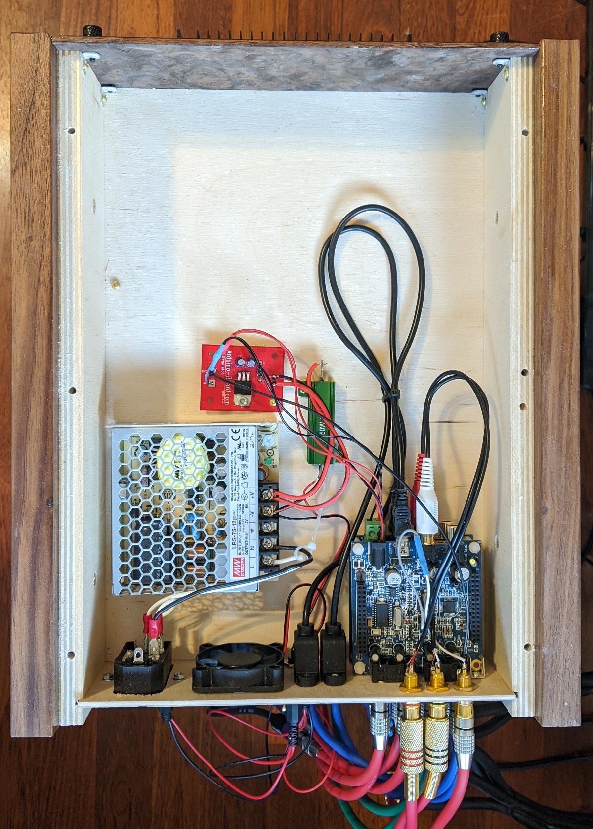
The crossover is a 4-way 48dB/octave LR with crossover points at 85Hz, 500Hz, and 5000Hz. It is implemented using one MiniDSP 2x4 kit per stereo channel, with the 4-way crossover plugin. The frequencies were chosen after testing the near-field response of each driver. The crossover also levels the outputs to get the same SPL from the sweep signal in each driver. The MiniDSP handles room equalization, and added a 0.02mS delay to the midrange. That is equivalent to 7mm distance. The acoustic center of the midrange is a little ahead of the tweeter. This brought the speakers to life. The sweet spot was about 5 feet off the floor at the listening position, but the delay moved it down to horizontal.
The power supply is a 12V switching supply. It doubles as a fan power supply for all seven fans. I added a 5V linear regulator board with filter capacitors to the output of the 12V supply and hooked that to the MiniDSPs for power. I tried a 5V switcher first, but that failed miserably. The power was just too ragged for the MiniDSPs to run on.
The rear panel has the IEC plug and the fan, along with two USB connectors for programming the MiniDSPs, the volume signal from the power control unit, left and right inputs, and the 8 outputs - 2 subs, 2 woofers, 2 midrange and 2 tweeters. While the front panel is the only blank one in the set, the rear panel is the busiest by far. The total cost was $221.52, with the majority ($160) being the 2 MiniDSPs. If you think that is expensive, look at the Linkwitz analog crossover at Madisound.
The disadvantage of an active crossover is the need for multiple amps, but the multiple amps can be justified by the overall design. An advantage is the ability to change rooms without spending yet another $300 or more on passive crossover parts to try to get the speaker to behave in the room, or $3000 making the room work with the speakers.
Power Amplifiers

The amplifiers were $40 each from an ebay store (wfyb) in San Diego. You can get the same amplifiers from a number of sources. I chose this amplifier, because I had been using one of them to drive the subwoofer for over a year, so I went with what was familiar. I chose this store because shipping from San Diego is quick, and I've had good experience with them. The amps are stereo, and are DC servo with speaker protection relays. The power supply is built in, except the transformer, of course.
I left the power on to the subwoofer for over a year, and one of the filter capacitors grew a big lump on the top. I was upset until I calculated that the capacitors had been powered up for almost 10,000 hours. That is about 4x the life expectancy of the electrolytics. I replaced both capacitors, and it is still in service as the subwoofer amp. That's why I have a power control unit.
The transformers are Antek AS-2222, 200VA 22VAC x 2. They cost $32.00 each and can source up to 5.6ARMS @ 40VRMS. The maximum the power supply can produce is 112W (40VRMS @ 2.8ARMS) per channel. The maximum the amp should consume is 47.5W (19VRMS @ 2.5ARMS) per channel into 8Ω. That does not count the power wasted by the amplifiers, which is about 24.5W each at its highest point. The transformer won't be the weak link in the chain.
Each amplifier drives one speaker in the left box with the left channel and the same speaker in the right box with the right channel.
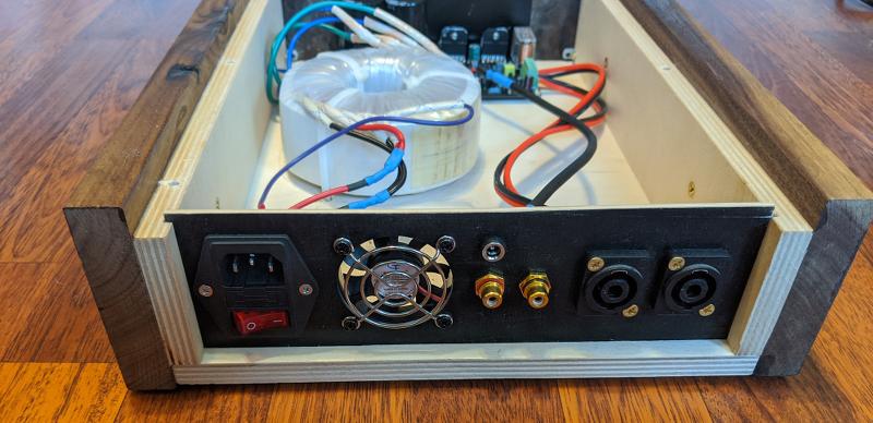
The rear panel has the IEC, fan and fan power connector, along with two RCA connectors and two Speakon connectors. The grille on the fan is a new requirement. I stuck my finger in one in the past and two blades broke off. The grilles are cheaper and more fun than than replacing a fan.
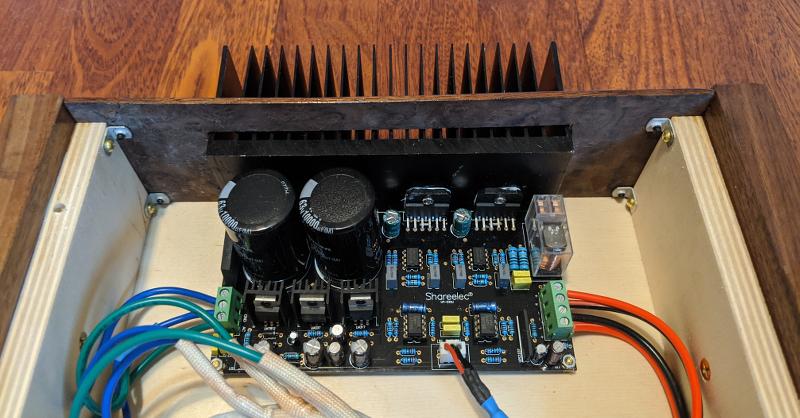
There is clearance around the heatsink and the heatsink is recessed so that while air is being exhausted in the rear, fresh air is pulled through the heatsink. It keeps the heatsink just a little over ambient. Without the fans, the heatsinks get warm, but more importantly, the regulator heatsinks on the amp board get hot. The trade-off is fans make noise. I've added 4Ω resistors in series with the fan power at the source, which cut the voltage to the fans, quieting them down.
With the amp boards, transformers, wiring, Neutrik connectors, fans, power inlets, and enclosures the main amplifiers ended up costing $126.24 each. Still inexpensive for the quality of sound.
Because models of amplifiers come and go, I bought a spare amplifier and transformer in case there is a failure down the road.
Subwoofer Power Amplifier
The subwoofer amplifier is essentially the same as the main amplifiers, but has added circuitry for the velocity feedback. The VFB board has an inverting amp that is used to make the power amp bridged. It supplies the right channel with an inverted version of the left channel.
The rear panel has the IEC plug, fan and fan power connector, along with left and right line level RCAs and two pairs of binding posts for the voice coils. The sub amp was more expensive because it has another transformer (50VA) and a custom PCB with the velocity feedback circuit on it. The total cost for the sub amp was $177.02.
Cables
Being trained in electronics, I know that as long as they have good specs, and don't fall apart, cables are pretty much cables. I wanted to clean things up a bit behind the stack, and that meant making shorter cables. I decided that since I'm making cables, I may as well try some of the better cable available. To that end, I bought some Mogami W2549 and W2552 from Performance Audio.
The Mogami cable is a joy to work with. It strips easily, and the insulation doesn't melt when you solder the wires. The cables are very flexible, too. These things alone make it worth the price. I can't hear any difference between the Mogami cables and the Monoprice cables I had been using, though. I'd like to, but it's just not there. However, I feel better knowing that I have less clutter.
Inside the units, both the Mogami W2549 in the preamp and the W2552 in the power amps made a significant difference over the cheap ebay cable I started with. After I rewired the preamp, a nagging little buzz was gone and the clarity was noticeably better. I rewired all of the amplifiers, and the upper mids and highs are again noticeably better. I suspect lower resistance, capacitance and inductance, which would all affect the mids and highs.
I know it made a difference in the preamp, and in the power amplifiers, but why didn't it make an audible difference in the interconnects? The interconnects were all Monoprice RG59-type cables. I took one apart and it has a copper 60% braid shield, a full aluminized mylar shield and a stranded copper inner conductor. I have since swapped the cables back and forth, listening for a difference, but no difference is heard. I guess a good cable is a good enough cable. Or rather there is a certain minimum below which a cable can be easily improved upon and above which it cannot. That is only true since the audio range is limited. I suspect Mogami's microphone cable doesn't work as well with very high frequency signals as the Monoproce RG59 cables do, since RG59 is designed and built for frequencies up to 50MHz or so.
The main speaker wire is a 12-2 stranded copper cable in a neoprene-looking jacket. Each is 3/8" O.D. and 10 feet long, with 4-pole Speakons on each end. There are four per speaker cabinet, color coded using colored cable ties. The subwoofer is wired with 14 awg copper zip cord terminated with Nakamichi connectors. Both the drive and the feedback use the same cable type, since they're interchangeable.
Afterthoughts
I should have practiced doing burl veneer on sacrificial front panels. I didn't do it as well as I had hoped. The front panels are 3mm ply with walnut glued to the edges, veneer applied to both sides, and then cut to size. It is important to get the walnut exactly the same thickness as the plywood because the veneer telegraphs the substrate. That is where I failed. The walnut was sometimes thicker and sometimes thinner than the plywood. Creative assignment of front panel to box position sort of saved me, as long as no one looks that closely. I might also plan on 1/4" front panels, rather than 3mm, so it would be easier to align the walnut strips to the plywood. Or just solid 1/8" or 1/4" panels, with or without veneer. Cost would be significantly higher.
I left too much wiggle room in the back panels. Too much left and right. I left reasonable slop in the groove, and then cut the panels undersize. One or the other was enough. It made assembly more difficult than it needed to be.
The rubber feet on the bottom unit prevented me from moving the heavy stack of boxes, so I had to put paper under the feet on the sub amp. I've since found some hdpe feet for a walnut base that will fix the problem.
I went with cheap RCA connectors. I doubt it makes a difference in the sound, because they have high retention force and they're gold plated, so they won't corrode, but it makes a difference in how easy or hard it is to assemble the things. It's Neutrik/Rean next time. The difference is $35 for 10 pair vs. $8 for 10 pair, but the frustration of dealing with the cheap connectors is not worth the money saved, in my opinion.
What started out as a pair of speakers evolved into a complete HiFi system, and as a system, it works well. The sound is as clear and detailed as I've heard. Multi-amping is a good way to get better sound. It is also a very difficult way. All of the idiosyncrasies of the individual drivers have to be accounted for, as do the room resonances. Luckily, there is a straightforward way to do that - adjust the amplitude response of the individual drivers to be equal, then tune out the room response at the listening position. Straightforward, not easy. I spent weeks of spare time tuning, then re-tuning to get it as "right" as I could. In the end, I think I did get it as good as I could in that room.