Front Panel
The front panel carries everything but the camera. The idea was to make it as simple as possible to get to the internals. 12 screws give full access to everything inside, including the front of the camera. It took several days to get the parts ready. The primer had to dry for at least 48 hours before I could put the black on, and I used flat black on one side and semi-gloss on the other. Actual time spent assembling the front panel was about an hour, after all of that.
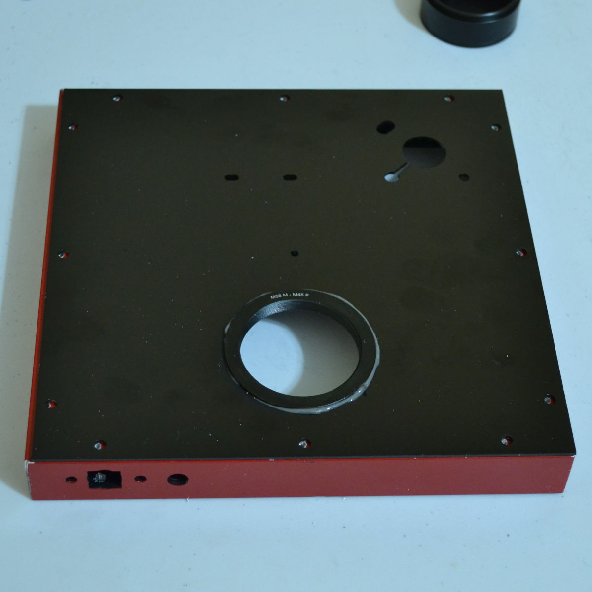
The painted front panel has the 56mm to 48mm adapter epoxied into the 56mm hole. The 4.5 pound weight of the filter wheel and camera is supported by that glue joint (and the interference fit), so it needs to be sturdy.
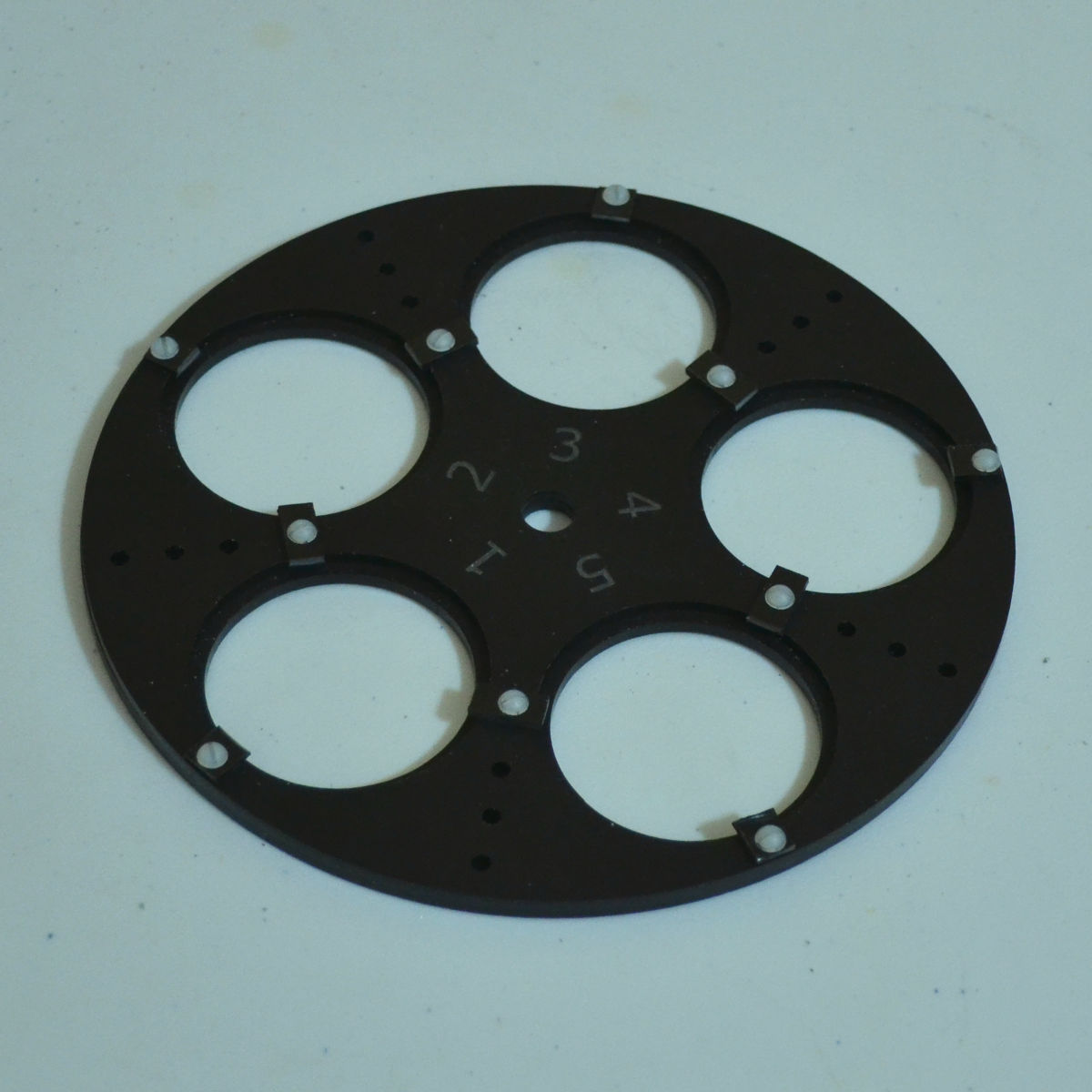
The holes were tapped and the 10 clips and screws were used to hold the two filter wheel halves together. The magnets were added in the proper places.

A piece of 2mm neoprene foam serves as an insulator for the PC board. Two screws hold the board in place. There are slots in the front panel to allow for sliding the board to center the filters.
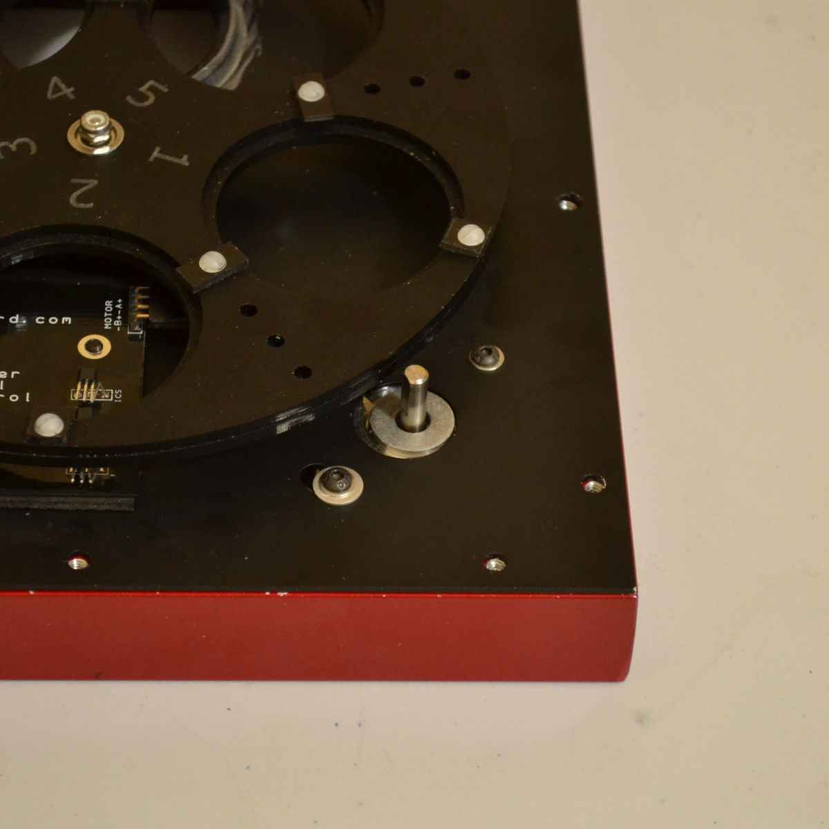
The stepper has a "D" shaped shaft. The tire would not be round, or long enough, if slipped over that.
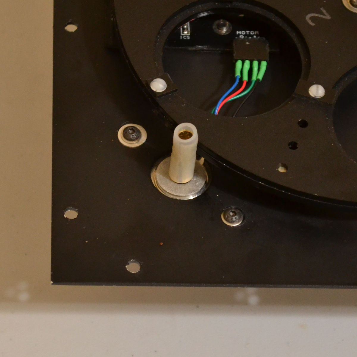
A 7/32" brass tube cut to length and slit up the side (for expansion) made the tire round. The brass tube was then slipped over the 5mm motor shaft.

The USB to serial converter is mounted with double-stick tape because it has no mounting holes. The Rx, Tx and Gnd wires route under the controller PCB to keep them out of the way.

Copyright ©2000 - 2026 David Allmon All rights reserved. | Privacy Policy | Cookie Policy