Project
The new filter wheel is done. You can find it on the Arduino filter wheel V3 page.
This goal of this project is to make a color filter wheel for astrophotography using an Arduino as the microcontroller. The wheel has positions for five 50mm round filters. It is motorized and interfaced to the camera, which is a QHY9S-M camera controlled by Nebulosity. Update: the camera is now an SBIG STF-8300EN, and the software is Indilib running on a Raspberry Pi 4B.
It is also a revamp of an old (ca. 2001) project which used older technology to achieve nearly the same end. An OOPIC provided the logic and a ULN2003 drove the stepper with help from lots of additional circuitry. The enclosure was 1/8" aluminum and the wheel was birch ply. All of the electronics were on the outside of the enclosure on two large boards. This time around I used an Arduino and an A3987 motor driver, and had the parts laser cut from bamboo plywood. The difference is half the cost, 10 times the speed, lighter weight, and better positioning accuracy with no LEDs in the enclosure. And the electronics are all inside and out of the way.
The wheel, with modifications, could be made to work with about any camera. There are two things to consider:
- The mechanical interface
- The electrical interface
The mechanical interface is simply how to bolt the filter wheel and camera together with the optical axes lined up. Electrical is probably just firmware. You need to read the commands from the controller and respond when complete.
Problems and Solutions
Problem:
The odds are against a stepper positioning a wheel in exactly the same place each time because a full revolution is probably not an integer number of steps. It is also unlikely there are the same number of steps between any two consecutive filters. The wheel is an inertial load, and as such likes to overshoot when stopping. Finally, when in use it is pitch dark and the enclosure is sealed, so there is no way to be sure the correct filter is in position.
Solution:
One solution might be detents which force the wheel to stop, but they are complex mechanically and I would rather have complex electronics or firmware than complex mechanics. Another solution is positional feedback. The feedback could have been in the form of LEDs and optical sensors, but having LEDs inside a telescope is generally a bad idea. I went with Hall effect switches and 1/8" diameter rare earth magnets. With a little firmware, the Arduino knows with some certainty that the correct filter is in place and in the same place it was last time. Acceleration and deceleration prevent missed steps on start and overshoot when stopping.
Problem:
The protocol stated in all of the documentation is 9600 baud serial, ASCII '0' through ASCII '4'. That would be LSB first. What actually happens is the 100 baud interface sends 16 bits of data: a byte of 0x25 and a byte of a binary value 0 to 4, all in MSB first. No ASCII, unless you say that the 0x25 is a '%' character.
Solution:
A "bit-banging" serial routine reads bits at 100 baud, inverts the data, reverses the bits, and skips over the 0x25, reading only the binary value.
Theory of Operation
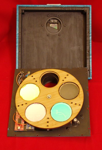
A wheel with bearings in the center turns on a fixed axle. It is driven by a motor and tire at the rim. Magnets are embedded in the wheel in patterns representing the position in binary code. The magnets are seen by Hall effect switches, which when read by the Arduino are used to determine the filter wheel's position.
To move, the position of the selected filter is calculated and a fudge factor is added to target the drive motor past the filter's position. As the wheel turns counterclockwise the filter magnets’ two edges pass the sensors. The Arduino records the position of the edges, and then stops the motor. The center position is calculated and the Arduino backs the wheel to the calculated center point. The center point will not be exactly the same for all filters, but that isn’t the problem that needed solving. The problem was one of each filter always positioning the same. That problem has been solved by locating the magnetic center of each filter and positioning that on the sensors.
When the unit powers up it seeks the first filter counterclockwise from the current position and centers on it. Once centered it reads the filter number and calculates the distance to filter 1. It then goes to filter 1 and centers. This process may take from 1 to 3 seconds, depending on where the wheel is when reset. When filter 1 is centered, the unit is ready to take commands from the camera. The commands are received and converted, and the controller then sends the wheel to that position.
There is a button that causes the firmware to reset the Arduino. I put that in in the event the Arduino gets confused about the current filter, but it has never happened, so I use it to tell if power is applied. By resetting it and listening for the wheel reset process above I can tell that it is ready.
When the camera initializes it sends the filter wheel to position 1. Scripting commands then select the filter as needed.
Hardware
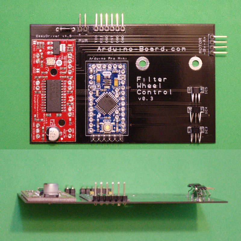
The electronics were chosen based on size more than anything else. They have to fit in a space that is approximately 1/4” high. The obvious choice for the Arduino was the Arduino Pro Mini from Sparkfun. It has a 16MHz ATmega328, and is made with a 1/32” PCB. There is a power LED that must either be removed or covered, but the pin 13 LED won’t cause problems.
The EasyDriver, also from Sparkfun, is a driver board with an A3987 stepper controller chip on it. It is on a 1/16” thick PCB, and has a capacitor that sticks up over the 1/4” limit, but it is at one end. It also has a power LED which has to be removed. For the LEDs I just heat one end with a very fine tip soldering iron and flip it up, breaking the connection. You could just as easily put a drop of black enamel model paint on it.
Rather than having a lot of space-consuming point-to-point wiring, I went for a 1/32" thick carrier PCB to hold the other two PCBs. There is no room for sockets, so the Arduino Pro Mini and the EasyDriver are soldered directly to the carrier PCB, which is daring considering that you can’t test it until it is assembled, and then it is too late. The boards can’t be desoldered easily or by normal means (a propane torch on the bottom works). I tested with clones of both the Arduino and the EasyDriver to be sure the board worked before committing to the more expensive Sparkfun products.
I used headers to register the boards on the carrier PCB. Soldering takes a very fine point iron, which is first used to solder the hole on the top board, then pushed through the hole vertically into the hole on the carrier PCB to solder the two holes together without any actual conductor between them but the solder.
The two large holes in the board are sized so that a #6 machine screw will thread into them, holding the board in place. Nuts would be impractical as the board position must be adjusted with the wheel in place.
Schematic

The schematic shows the Arduino Pro Mini with the EasyDriver board along with the three Hall devices. A blocking diode is used so there is no damage if the power is connected backwards, which I have been known to do. The Arduino controls the STEP, DIRECTION, and ENABLE lines to the EasyDriver, and the EasyDriver supplies the 5V for the Arduino.
A 2-wire cable goes to the reset switch, one to the power, and another to the serial connector for the camera. The power supply is a 9V 2A wall wart. I chose 9V as a compromise between high torque and low heat in the voltage regulator. Reliability was more important than speed, although at 4000 steps per second it is pretty fast. The EasyDriver can accept 6V to 30V, but the 5V regulator has to drop that down to 5V and all of that power is dissipated there. The motor is turned off when not in use, so the driver chip won't get hot.
Mechanical

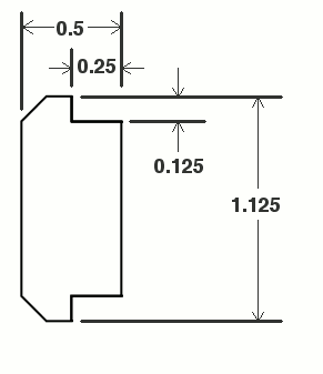
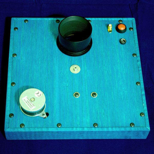
The enclosure sides are made from 1-1/8" x 1/2" maple. They were shaped on a router table and cut to length with a miter saw. Please note that the 0.125" dimension is actually the thickness of the panels, which in my case was 0.106". Glue up is identical to a picture frame. I added little glue blocks at the corners for strength. The glue was Elmer's Exterior (waterproof) since the humidity can get high outside sometimes. After the sides were glued up, the front and back were fitted by sanding the edges a little. The front and back were used as templates for drilling the 1/8" holes in the sides. Thanks to the miracle of modern science (and the precision of the laser cutting) all of the holes lined up front and rear and the holes met in the middle. I used #6-32 x 3/8" truss head screws to secure the front and back - 16 per side. They will self-tap in the 1/8" holes. Only the front is intended to come off again. Since the filter wheel is built on the front, taking it off takes all of the internals with it. The camera is screwed to the back panel with 6 M3 x 6mm screws.
The nose piece is a 2" to M42 (T-thread) adapter. It is a tight fit in the panel, and is epoxied as well. It accepts 2" eyepiece filters, which is an important part of the filter. It allows you to install a UV/IR cut filter so the colors don't get skewed by the out-of-band IR light.
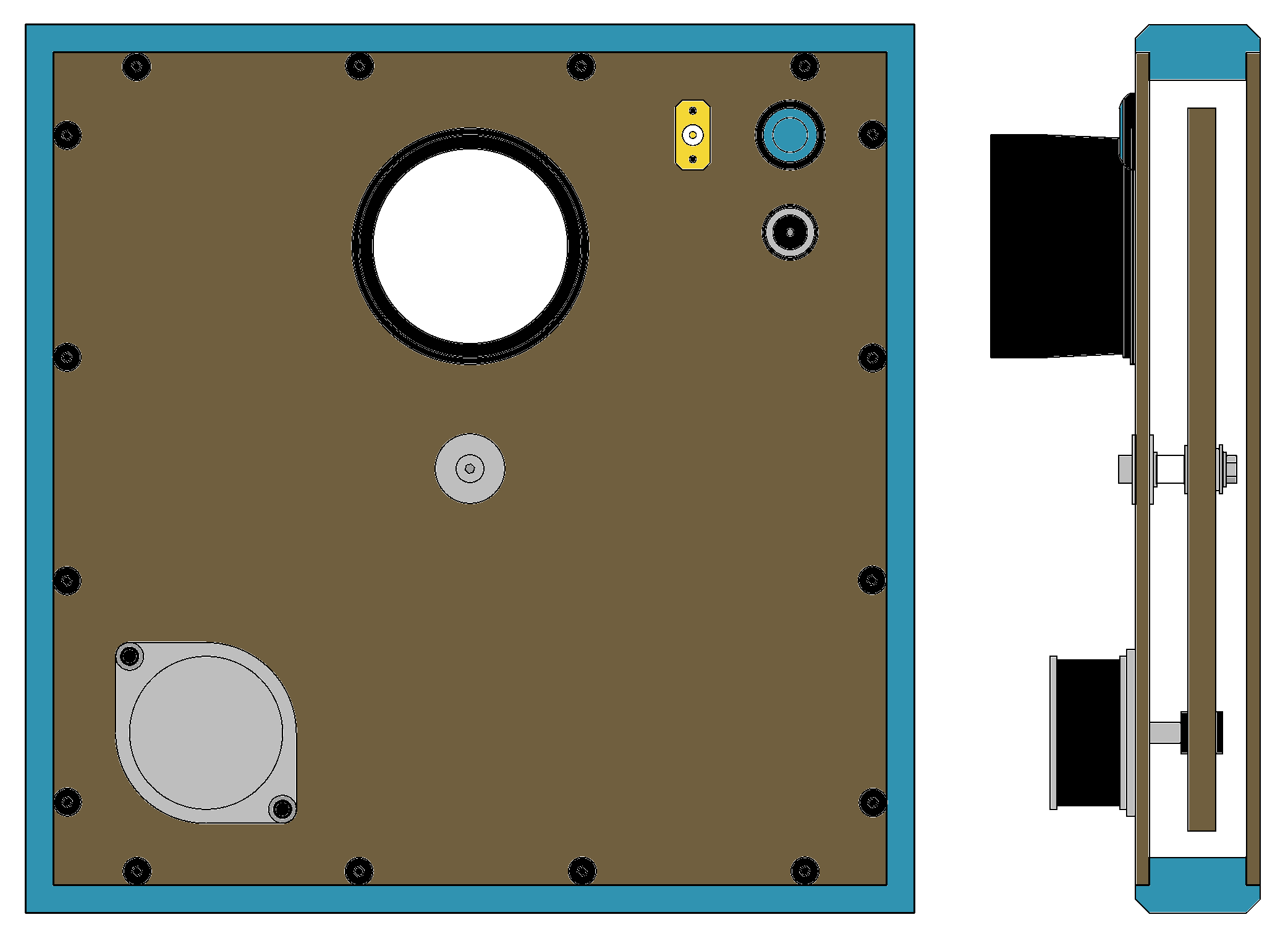
This drawing of the mechanical parts shows more or less how they fit together. The blue is maple, brown is bamboo plywood, and most of the rest is either aluminum or steel. The white spacer on the wheel's axle is nylon. The two bearings together are 0.25" thick, but the plywood wheel is only 0.213" thick, so the bearing sticks out away from the surface on the rear side of the wheel. They are expoxied, and the axle is the correct length for the bearings, so all is well. If you use too much epoxy they will not be bearings any more. I used less than a drop of epoxy for both bearings combined.
The axle is a shoulder bolt. It has a 1/8" diameter x 3/4" long shoulder, with a 4-40 thread at the end that is 5/32" long. The overall internal length is practically 7/8", so with the 1/8" nominal panel thickness, 1-1/8" is the enclosure outside depth front to rear. There is a #6 fender washer on each side of the front panel to protect it from the compression from the nut. Two more #6 washers take up some extra room to make up for the thinner front panel. Then the 1/4" dia x 1/4" long nylon spacer gives the room for the electronics. The wheel is the top of the stack and is held in place by a split lock washer and nut.
The motor needs a tire to turn the wheel. I went to the hobby store and found an aluminum tube that wouldn't quite fit on the motor shaft. I cut a piece long enough to extend the motor shaft the correct distance, and then split it with a single cut on one side up the length using a razor saw. This makes the tube expandable. Then I epoxied a silicone HO scale race car tire to the tube in the right position to hit the wheel. There needs to be a little bead of epoxy on both sides of the tire on the tube in order to keep it from sliding up or down. Epoxy doesn't make a permanent bond with silicone, so the beads are the only thing holding the tire in place.

The filter wheel itself is glued up from two parts, one having five holes larger than the diameter of the filter and one having five holes smaller than the filter. The two together make a well that holds the filter. Two bearings are used in the center of the wheel for stability. There are three 1/8" diameter holes per filter for the magnets. The magnets are located opposite the filter, so they are over the sensors on the PC board when the filter is in the optical path.
The filter wheel was glued up using a piece of 3/8" dowel and a piece of 1/8" dowel to pin-register the parts. They were clamped between two 3/4" thick MDF cauls overnight in an attempt to assure flatness. One set came out flat and one didn't. There are two kinds of bamboo plywood offered at Ponoko - one blonde and one amber. The amber one is charred a little to change the color. It appears to start out as the outermost layer of the bamboo, and it is hard. The blonde one appears to be from inner layers, and is a bit softer. This may only be the pieces I received or it may be the way it has to be to manufacture it. I ordered two sets of each, and both of the blonde ones were warped pretty badly, but the amber ones were perfectly flat. I used the wheel parts from the amber set and the panels from the blonde set, since the panels are so firmly affixed to the side panels. If I did it over, I would forego the blonde altogether.
I put a dab of RTV in two places on each filter, but only because these filters are 20 years old and were already glued into another wheel. In the real world I would use small pieces of sheet PVC and nylon screws to hold the edges. There is room between the wheel and the camera side to clear if the clips are thin. The screws should be nylon so as not to affect the magnets that sense the wheel position. I would put them at the narrowest point between the filters, with each clip holding the edge of two filters. The holes for the screws will need to be tapped, because you can't self-thread with a nylon screw.
The following files are part of this project:
If you are going to use these files, be sure you are careful. Having these parts made can get very expensive. The bamboo parts are just over $26.00 per set, and there are no spares. PC boards can cost from $27 to $120. Inspect the files carefully, and don't accept copies from other sources.
UPDATE:The camera (QHY9S-M) freaked out and wanted a response from the filter wheel. The camera doesn't have a receive line - only transmit. I changed the interface from the direct camera interface to a QHYCFW1 interface, which is real serial, and added a USB to serial converter. It all started working again. For about ten minutes. Then the camera's USB interface crashed and it is no longer recognized by the computer. I'm waiting for a new camera - an SBIG STF-8300EN, which is about as direct a replacement for the now obsolete QHY9S as one can get. The filter wheel, now that the interface is separated from the camera, will work with the new camera as is, too.
