Filter Wheel Project
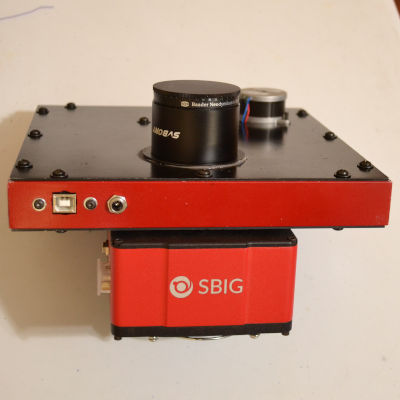
This is my third filter wheel, and the second using an Arduino Pro Mini. I replaced all of the wooden parts from version 2 with either aluminum (for the box), or acrylic (for the wheel). The electronics are the same as the previous filter wheel, with the exception of the reset switch, which was not used. I also added an internal USB to Serial converter so the filter wheel can be run directly by USB, rather than through an external converter.
The thing that made this new version possible was the ready availability of laser cutters capable of cutting aluminum. When the first was made there were no laser cutters, and when the second version was made there was no inexpensive laser cutting for metals. The wheel parts could not be made from aluminum because the design calls for holes that are too small for the metal cutting laser's design rules. I used Ponoko.com for all of the laser cut parts.
Mechanical
The front panel has the stepper, electronics, and a means for attaching the filter wheel to the telescope. A 56mm hole takes a male 56mm to female 48mm adapter from Agena Astro. That lends some flexibility to mounting, using either a 48mm to 2" nosepiece or a 48mm "wide-T" tube for threaded attachment. In some cases they are the same thing. The 48mm to 2" nosepiece is SVBONY, and the cap to cover it when the filter wheel is off the telescope is from Agena Astro.
The back panel only has the camera mounting pattern on it - a 48mm hole and 4 screw holes. If I change cameras, the only part that needs to change is the back panel, either by replacement or modification of the current panel. The front and back panels have 12 screws each that fasten them to the side frame.
The frame is made from 1" extruded aluminum channel. The corners are mitered and epoxied with Permatex Steel Weld epoxy. All of the aluminum parts have a coat of aluminum primer and are painted black or red.
The axle is a 0.125" x 0.75" shoulder bolt that goes through the front panel, a 5/16" long spacer, one flanged bearing (FR2-ZZ), a 3/8" brass washer, the wheel, and finally another bearing. A #4 Nylock nut and lock washer hold it all together. The brass washer makes a space between the two bearings, so the nut can load the bearings. The Nylock nut allowed me to set the compression on the bearings low, without spinning off.
A Baader Neodymium Moon & Skyglow filter is on the nosepiece. The color separation filters are a set of Edmund Optical 50mm unmounted RGB dichroics and a clear, AR-coated luminance filter. The 2mm thick color filters sit on o-rings - the 3.3mm thick luminance filter does not. The filters stand out of the wheel by a fraction of a millimeter. The ABS clips provide enough pressure to hold the filters in place, but not enough to stress them. Non-magnetic Nylon screws hold the clips.
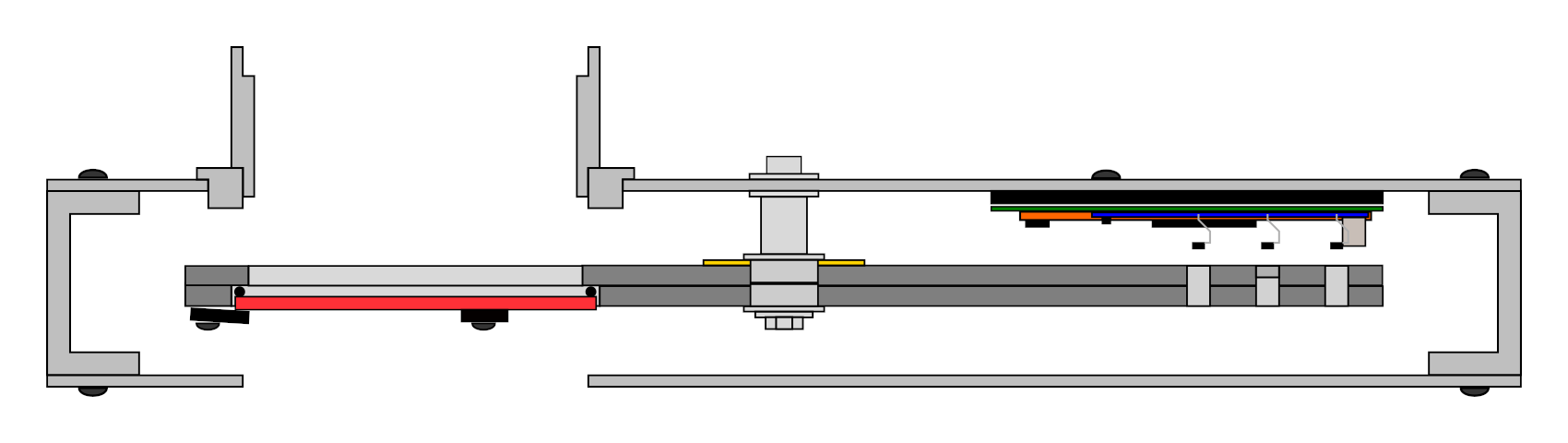
The drawing above shows how the parts relate to each other. The front panel is up. The camera would be on the bottom. The filters and electronics are accessible by removing the front panel, pulling the electronics and filter wheel with it. It shows the 15mm nosepiece, but I decided on the 30mm nosepiece since it didn't affect the vignetting any.
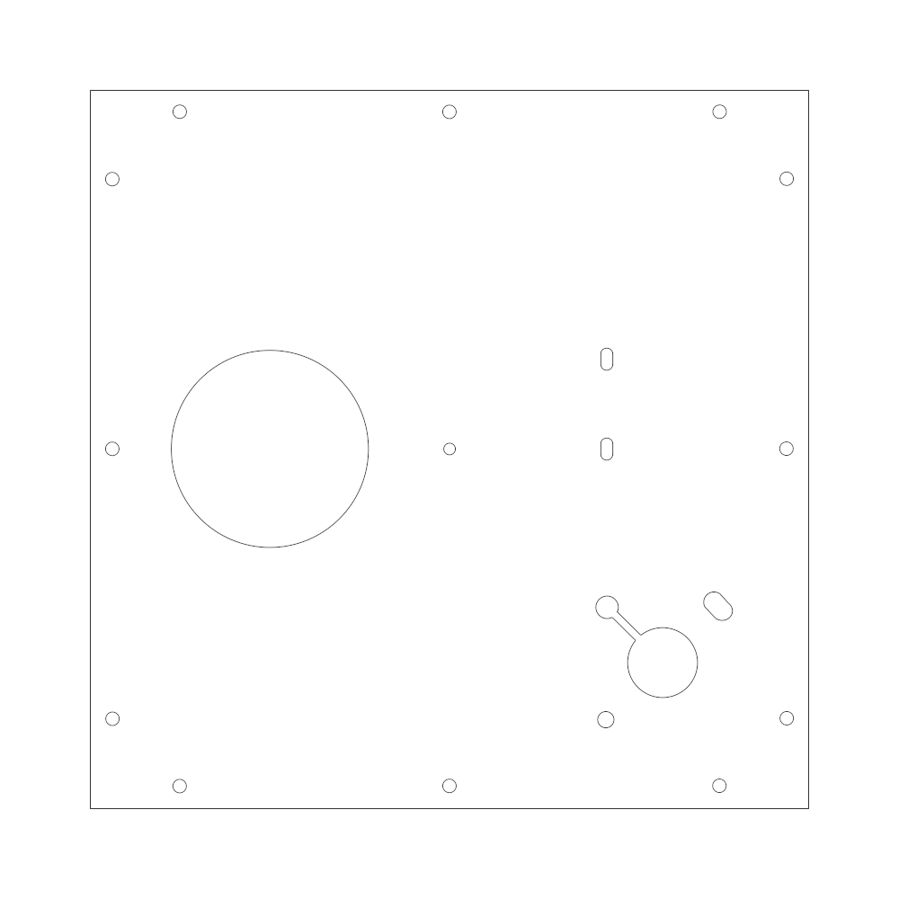
The front panel carries all of the mechanics and electronics. It is laser cut from 0.063" aluminum.
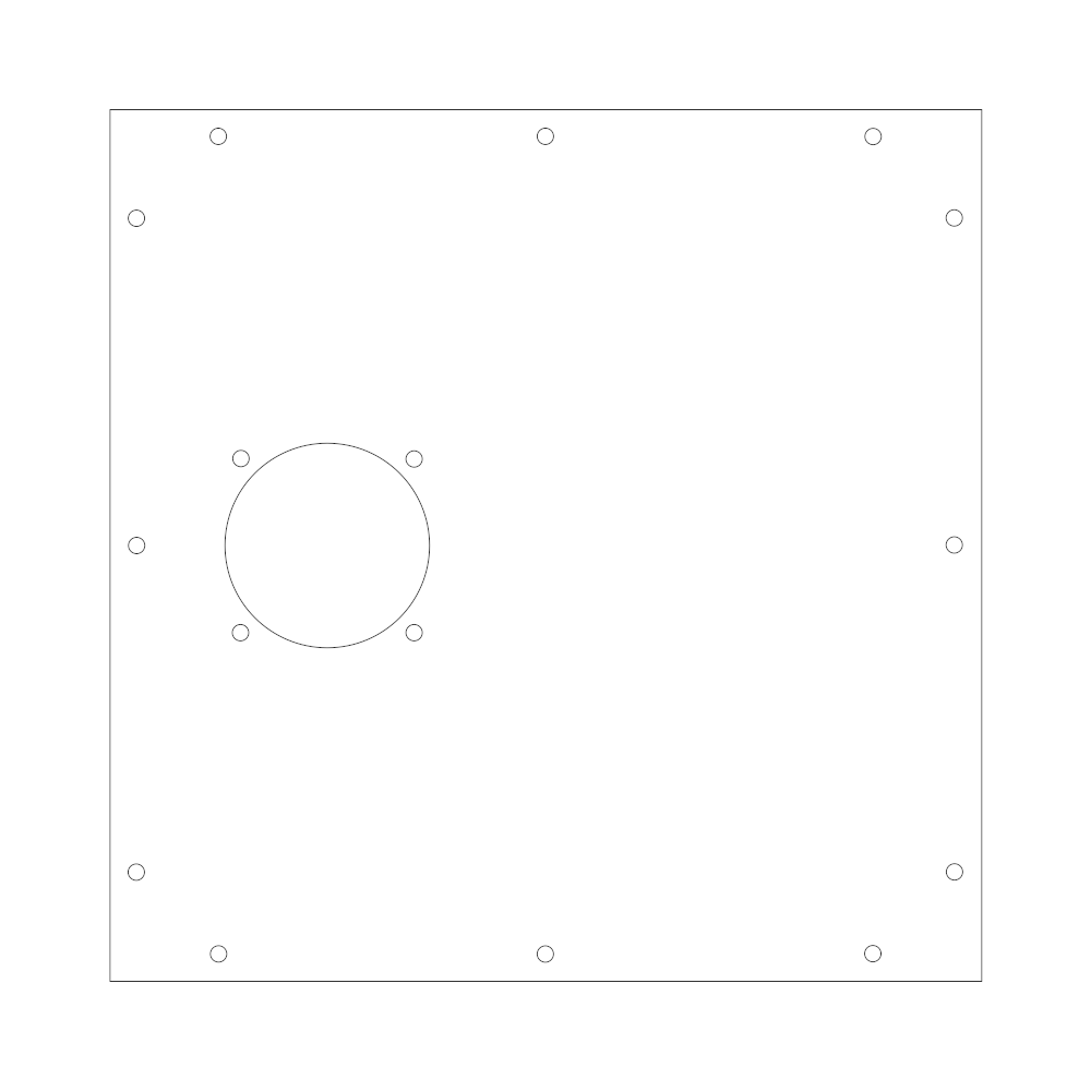
The back panel has only the camera mount. It is also laser cut from 0.063" aluminum.
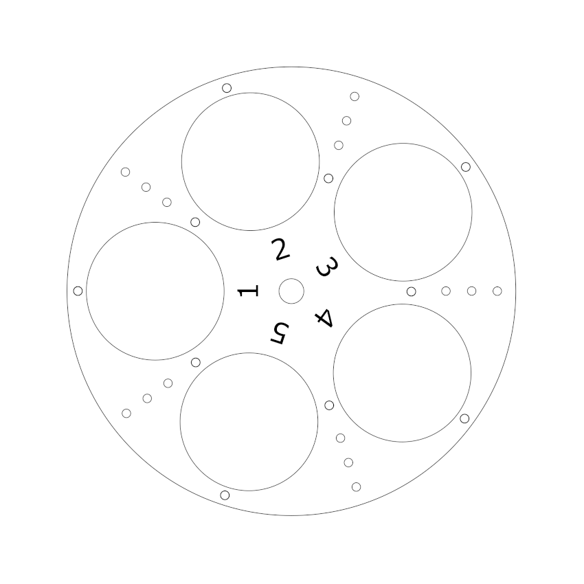
The rear wheel is the one facing the camera. It is 6.5" in diameter and made from 0.125" acrylic, with 51mm filter holes.

The front wheel is nearly identical in appearance to the rear wheel, but has 46mm holes to support the filters at their edges.
Electronics

The filter position is sensed by Hall effect switches that detect magnets placed in a 3-bit binary pattern around the wheel. The controller locates the correct filter and then centers it by finding the width of the magnetic field, and splitting it. The filters are always approached from the same direction, passed, and then backed up to center.
Another difference between this wheel and the last one is the drive ratio. It was ~15.76 for the old one, and the new one is ~20.3. The difference is in the tire used. V2 used a 10mm diameter H.O. scale slot car tire, while V3 uses a length of silicone tubing, which is only 7mm in diameter. That changed some constants in the program, slowed it down a little bit, and gave it more resolution.
/***********************************************************************************
 * qhycfw1v3.ino
 *
 * 5-position color filter wheel
 *
 * Inputs:
 *
 * 3 Hall effect switches on A0-A2
 *
 * Ouputs:
 *
 * STEP on pin D2
 * DIR on pin D3
 * EN on pin D4
 *
 * On power up it looks for filter 1 and centers it.
 *
 * The motor makes ~20.3 turns per turn of the wheel, or 16250 half-steps per turn.
 **********************************************************************************/
#include <AccelStepper.h>

#define QHYCFW1 1
#define QHYCFW2 2

#define MAX_SLEW_SPEED 4000
#define MAX_SLEW_ACCEL 40000

// The motor instance.
AccelStepper motor(AccelStepper::DRIVER, 2, 3);

// Motor enable pin.
uint8_t enablePin = 4;

// The currently selected filter.
uint8_t currentFilter = 0;

// How far to run when skipping 0, 1, 2, 3, or 4 filters.
long positions[5] = {0, 3250, 6500, 10150, 13450};

// A fudge factor to drive past the filter while reading the
// filter index edges.
long overshoot = 500;

// There is a problem with the QHYCFW1 indi driver.
uint8_t model = QHYCFW2;

// Reset vector so we can do a software reset.
void (*reset)(void) = 0;

/******************************************************************************
 * findFilterTrailingEdge()
 *
 * Finds the trailing edge of the first filter it sees.
 *
 *****************************************************************************/

void findFilterTrailingEdge() {

    // If the wheel is stopped in between filters,
    // run to the next filter.
    if (currentFilter == 0) {
        motor.move(positions[1]);
        while (motor.run() && (currentFilter == 0));
    }

    // Run to the trailing edge of the filter index.
    motor.move(positions[1]);
    while (motor.run() && (currentFilter != 0));
    motor.stop();
    while (motor.run());
}

/******************************************************************************
 * findAnyFilter()
 *
 * Finds the center of the first filter it sees.
 *
 *****************************************************************************/

void findAnyFilter() {

    int distance = 0;
    long steps = 0;
    long begin = 0;
    long end = 0;
    long center = 0;

    // Are we on a filter?
    if (currentFilter != 0) {
        // Go find the trailing edge.
        findFilterTrailingEdge();
    }
    // Look (one filter spacing + fudge) ahead for a
    // filter index to start.
    steps = positions[1] + overshoot;

    motor.move(steps);
    while (currentFilter == 0) {
        motor.run();
    }
    begin = motor.currentPosition();

    // Find the end of the filter index, then go to
    // the center of the index.
    while (currentFilter != 0) {
        motor.run();
    }
    end = motor.currentPosition();
    motor.stop();
    while(motor.run());

    center = (end + begin) >> 1;
    motor.moveTo(center);
    while(motor.run());
}

/******************************************************************************
 * runToCenter(int filter)
 *
 * Runs to the specified filter and centers.
 *
 *****************************************************************************/

void runToCenter(int filterNo) {

    int distance = 0;
    long steps = 0;
    long begin = 0;
    long end = 0;
    long center = 0;

    // Do we need to move at all?
    if (currentFilter != filterNo) {

        // If not on a filter, find one and center it.
        if (currentFilter == 0)
            findAnyFilter();

        // Figure out how far (in filters) to the target.
        if (filterNo > currentFilter) {
            distance = filterNo - currentFilter;
        } else {
            distance = 5 - currentFilter + filterNo;
        }
        // Convert to steps and add the fudge.
        steps = positions[distance];
        steps += overshoot;

        // Run to within 'overshoot' steps of the target.
        motor.setCurrentPosition(0);
        motor.move(steps);
        while (motor.distanceToGo() > (2 * overshoot)) {
            motor.run();
        }

        // Run until we hit a filter index and
        // mark the position.
        while (currentFilter == 0) {
            motor.run();
        }
        begin = motor.currentPosition();

        // Run until we are past the filter index and
        // mark the position.
        while (currentFilter != 0) {
            motor.run();
        }
        end = motor.currentPosition();

        // Stop the motor, and back up to the center of
        // the filter index.
        motor.stop();
        while(motor.run());
        delay(25);
        center = (end + begin) >> 1;
        motor.moveTo(center);
        while(motor.run());
    }
}

/******************************************************************************
 * findFilter1()
 *
 * Finds the center of filter1.
 *
 *****************************************************************************/

void findFilter1() {

    // Get to the center of a filter - any filter, so
    // we know where we are.
    findAnyFilter();

    // Go to the center of filter 1.
    runToCenter(1);
}

/******************************************************************************
 *
 * pciSetup()
 *
 * Setup pins for pin change interrupt.
 *
 *****************************************************************************/

void pciSetup(uint8_t pin) {

    *digitalPinToPCMSK(pin) |= bit(digitalPinToPCMSKbit(pin));
    PCIFR |= bit(digitalPinToPCICRbit(pin)); // clear any outstanding interrupt
    PCICR |= bit(digitalPinToPCICRbit(pin)); // enable interrupt for the group
}

/******************************************************************************
 *
 * setup()
 *
 *****************************************************************************/

void setup() {

    // Start the camera interface.
    Serial.begin(9600);

    // Enable pull-ups on Hall switch inputs.
    digitalWrite(A0, HIGH);
    digitalWrite(A1, HIGH);
    digitalWrite(A2, HIGH);

    // Enable the sensor pin change interrupts.
    pciSetup(A0);
    pciSetup(A1);
    pciSetup(A2);

    // Setup the motor.
    motor.setEnablePin(enablePin);
    motor.setMaxSpeed(MAX_SLEW_SPEED);
    motor.setAcceleration(MAX_SLEW_ACCEL);
    motor.setCurrentPosition(0);
    // (directionInvert, stepInvert, enableInvert)
    motor.setPinsInverted(true, false, true);
    currentFilter = (PINC & 0x07) ^ 0x07;

    // Go to filter 1
    motor.enableOutputs();
    findFilter1();
    //motor.setCurrentPosition(0);
    //motor.moveTo(4100);
    //while(motor.run());
    delay(10);
    motor.disableOutputs();
    delay(5);

}

/******************************************************************************
 *
 * loop()
 *
 * Reads one ASCII character ('0' to '4') from the camera and converts it to a
 * binary 1 - 5 value to match the magnets on the filters.
 *
 *****************************************************************************/

void loop() {

    uint8_t ch;

    if (Serial.available()) {
        // Get the command from the host as ASCII "0" to "4",
        ch = Serial.read() + 1;

        // Is it a filter ('1' - '5')?
        if ((ch > 0x30) && (ch < 0x36)) {

            // Turn on the motor current.
            motor.enableOutputs();

            // Go to filter 1 through 5
            runToCenter(ch - 0x30);

            // Let the wheel stop completely.
            delay(25);

            // Disable current to motor.
            motor.disableOutputs();
        }
        if (model == 1) {
            Serial.write('-');
        }
        else if (model == 2) {
            Serial.write(ch - 1);
        }
    }
}

/******************************************************************************
 *
 * Pin change interrupt for the Hall switches.
 *
 * Sets 'currentFilter' to the binary value of the magnetic switches.
 *
 *****************************************************************************/

ISR (PCINT1_vect) {
    currentFilter = (PINC & 0x07) ^ 0x07;
}
The host (a Raspberry Pi 4) talks to the filter wheel via a QHYCFW2 interface. The host sends a single character, '0' - '4', and the controller moves filter 1 - 5 into position, then responds with the same digit. The protocol supports 16 filters ('0' - 'F') but my implementation has five filters ('0' - '4'). The filters are luminance, red, green, blue, and one empty so I can reach the sensor with a cleaning swab when I need to.
Build
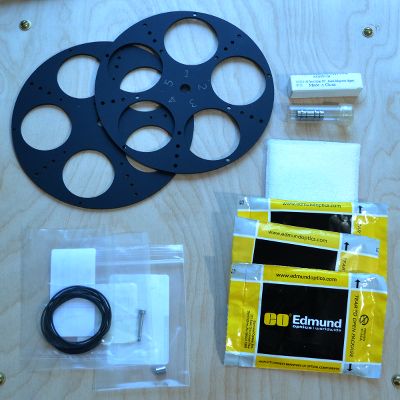
All of the parts are in.
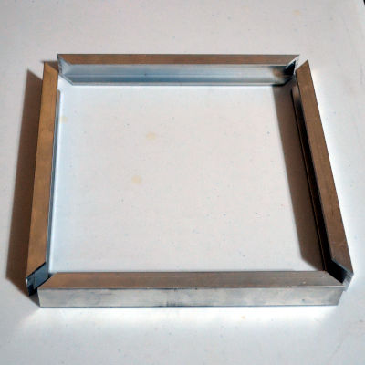
Cutting the sides and building the frame from 1" x 1/2" channel.
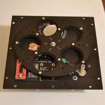
The front panel and all of the electronics and mechanics.
Assembly of the front and rear panels to the sides, hooking up the cables, and buttoning it up.