DIY Servo Subwoofer Amp Build
These are some build pictures of the subwoofer amp and feedback filter.
Enclosure
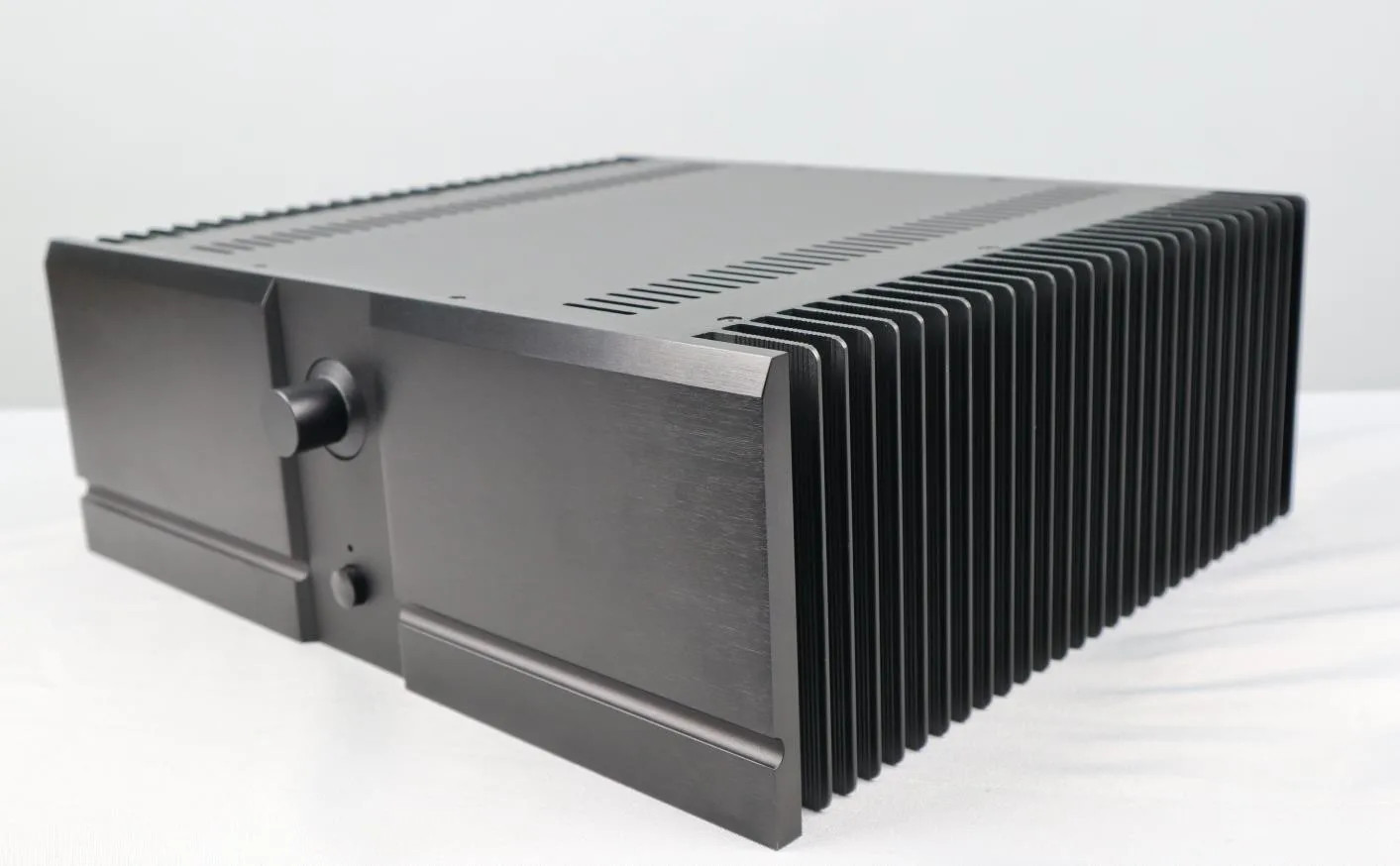
The enclosure came from AliExpress, and is the most expensive part of the project. It is a very solid box. Worth the money, I think. I picked it because it was large enough for this project, and a 100W per channel MOSFET amp, and I wanted matching boxes for the two. Obviously you could put it in any box or use any power amplifier. The amplifier is not modified in any way.

This is the layout I ended up with. It offers the most logical path between modules. The box marked POT at the bottom is the stepped attenuator I chose for the input level control. I decided on it because the steps are discreet, and when I bump it, it won't change the level. The level is for adjusting the volume to match the main stereo amps and speakers. If I change speakers or amplifiers, I'll have to turn that knob. The little transformer on the left is for the protection board, The VFB filter boards run off of the two 15V secondaries on the power transformer. The amplifiers are mounted on the back half of the heatsinks.
Power Supply

The 400VA transformer is from AnTek. It has 2x 34V@5.9A secondaries, and 2x 15V@2A secondaries. The big ones feed the amplifier through the rectifier board (right), and the 15V secondaries feed the VFB filter board. The main supply is ±46VDC for the amplifier, which will just allow for 100W into 8 ohms. 100W into 8 ohms yields 3.5A, at a voltage of 28VRMS across the speaker. The power transformer's main secondaries are nominally 5.9A, but are rated for 20% more at 60Hz.
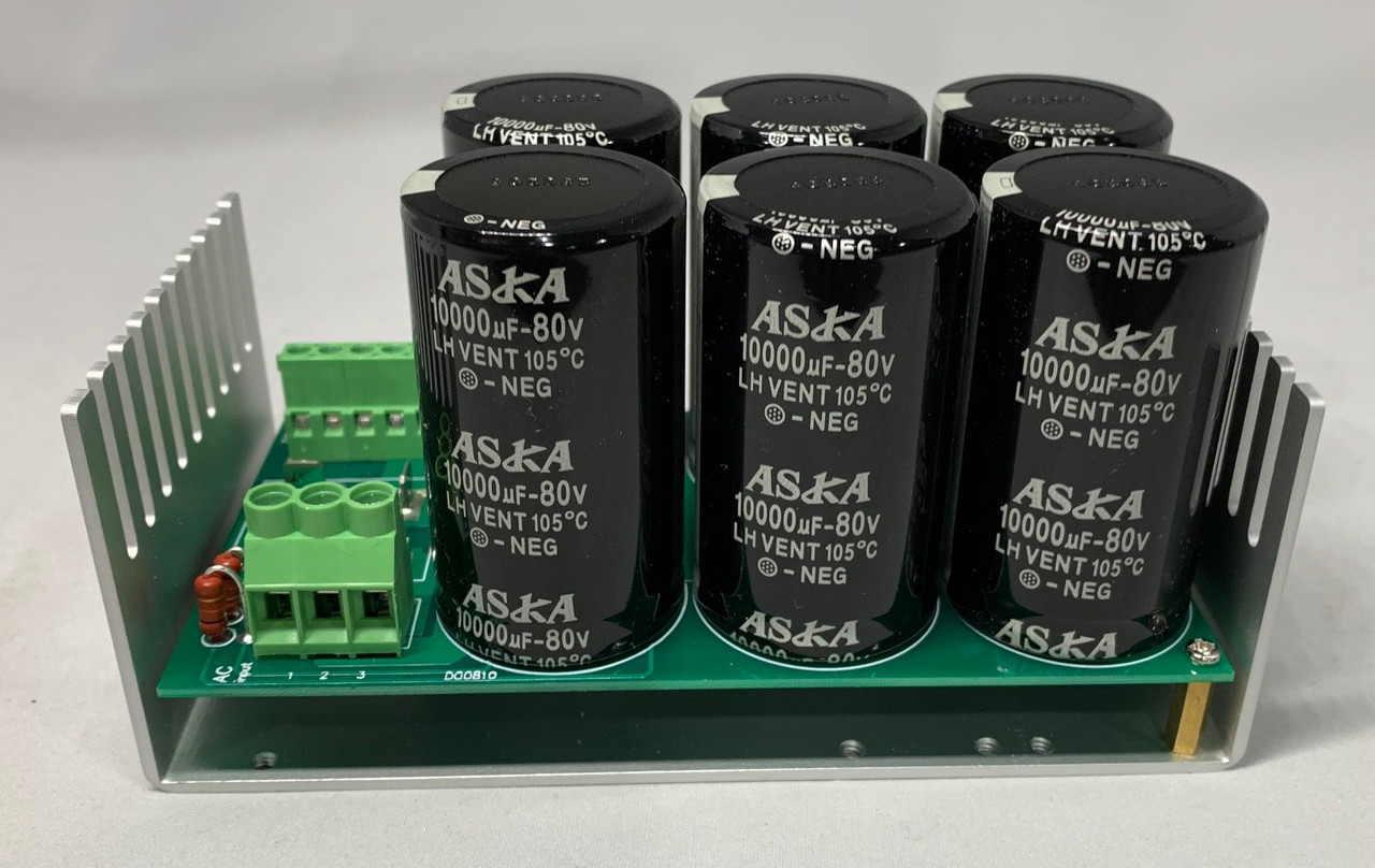
I used a rectifier/filter from AnTek, because it costs less than my cost of the capacitors that are on it, and it really is a 50A rectifier, with a huge heatsink. At 63V it is rated 40A. It can handle the job very well. The capacitors are 15,000μF/63V rated.
Electronics
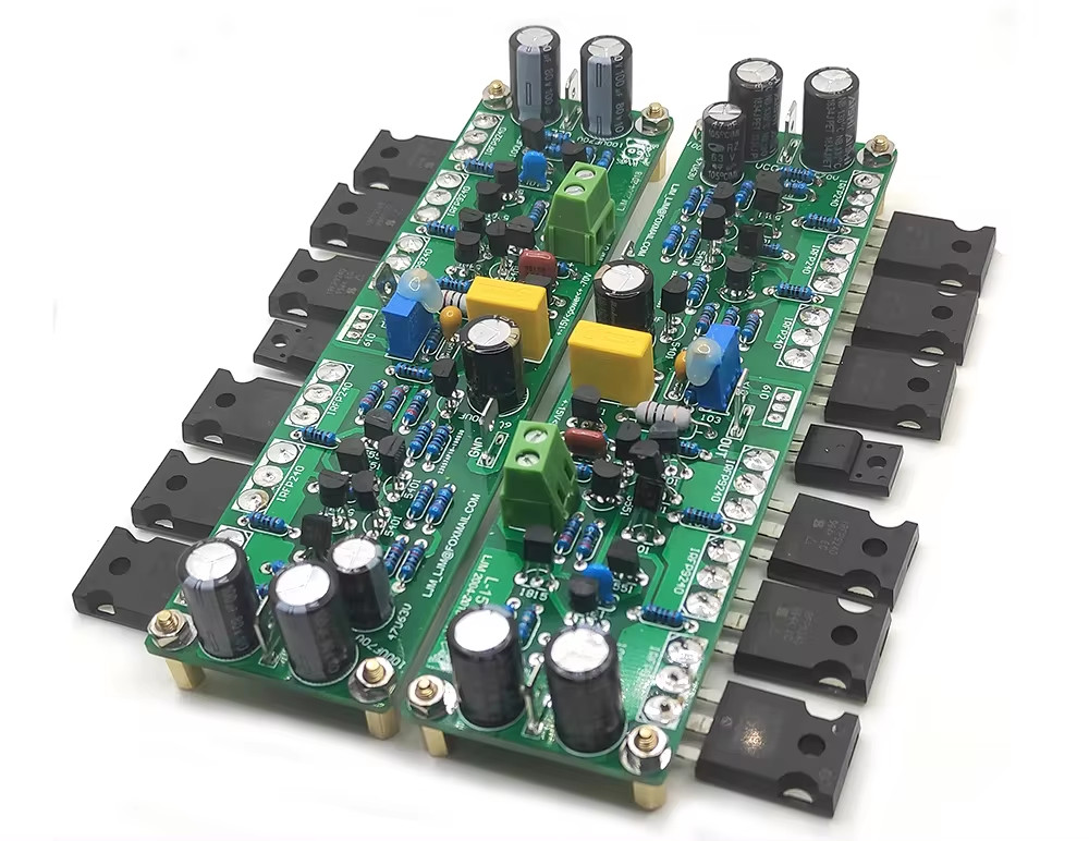
The amplifiers are 150W MOSFET amps running at a lower voltage for 100W each. These are the same as used in the main amp. They are LJM L-15's.
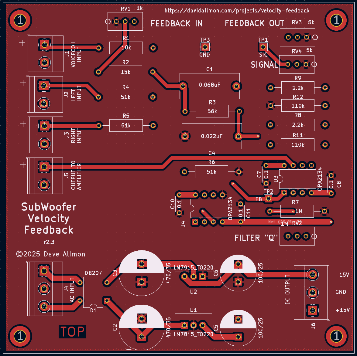
The velocity feedback board takes the low-level (L or R) or (L and R) input and one of the two subwoofer speaker cables as inputs, and outputs an error signal to drive the power amp. The amplifier drives the other speaker cable. See Velocity Feedback for specifics, like how to adjust the circuit.

I couldn't find a delay-only relay board that I liked, so I built this one to run off of 18VAC and do most of the things the μPC1237 does, and a little more. The delay is programmable via the Arduino Nano V3. For this project, I wanted a 3-second delay to allow the output to stabilize before connecting the speaker. It controls a relay for the speakers. You can see the speaker protector project to get further details on what it does. The speaker relay is mounted on the rear panel of the box.

----


Modified: 2024-09-26