SubWoofer with Velocity Feedback
This article has been updated since it was first published in 2021. I made a second pass at the filter, simplifying it considerably. Now it is just a 2nd order low-pass filter with adjustable Q, so the dip in the response can be lessened and the phase shifted.
Expectations
One side effect of velocity feedback is it can lower the cutoff frequency below the driver and cabinet resonance. With feedback this 10" subwoofer has response down to 10Hz, flat to within ±1.26dB with tweaking. This sub is just for music, and not for special effects. I would want a 15" sub for home theater. Also, keep in mind that this feedback will not help on a ported speaker box. The port will change the ratio between cone motion and loudness at different frequencies. The amplifier will cause a huge peak at the port/cabinet resonance, in an effort to keep the cone velocity up.
Box and SD270A-88 Driver Response
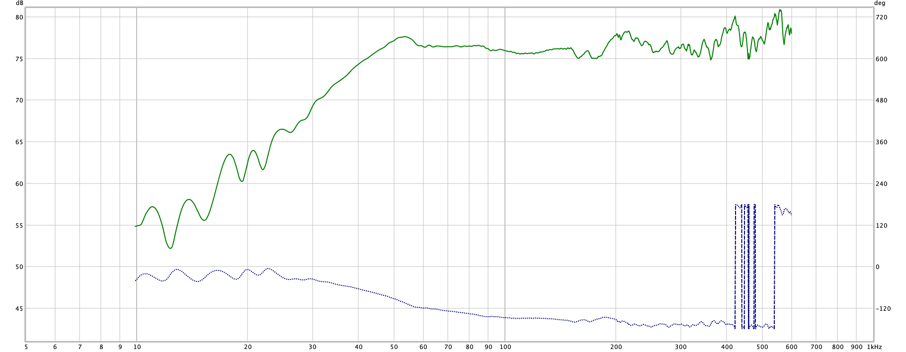
Plot of the driver in the enclosure, without velocity feedback. The woofer is in an enclosure with an internal volume of 73 liters, giving QTC = 0.669, f3 = 43Hz. The free-air resonance of the Dayton Audio SD270A-88 is 26.2Hz.
A dual voice coil driver has two nearly identical windings on the same coil form and moving in the same magnetic field. One coil can be driven and the other used to provide velocity feedback, if the feedback signal is compensated [1]. My plots do not look exactly like theirs, because their velocity is coil voltage w.r.t. laser-measured velocity (an error signal), where mine is absolute coil voltage with a zero reference.
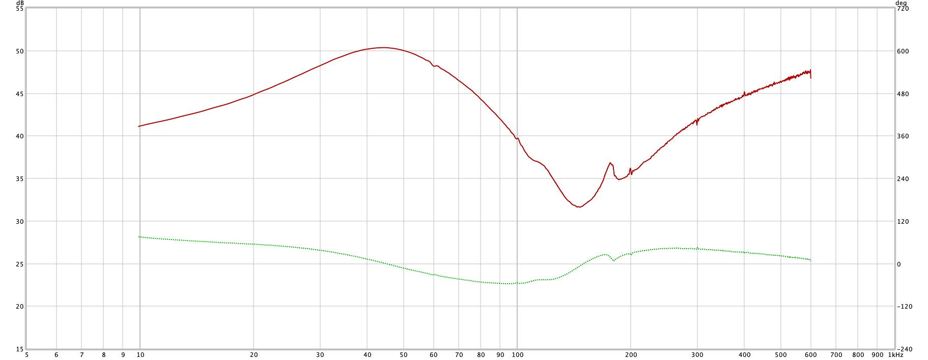
With any dual voice coil low frequency driver, the signal is not really a perfect match to the velocity of the cone. There is mutual inductance between the two coils that causes a 180° phase shift and a dip in the amplitude response. The frequency and amplitude of this phenomenon is different for each driver.
The disturbance in response can be counteracted by a 2nd order filter, with f0 = 146Hz. That puts the feedback more in line with the actual cone velocity. It will work without the filter, but it won't be anything near flat response. In fact my first pass at velocity feedback, in 1995 or so, was a 15" Eminence DVC woofer with a 25W amp I cobbled together using 2N6055 and 2N6053 Darlington transistors, and straight feedback from the voice coil. I dropped the whole mess in the cardboard box the driver came in and man did it sound good. Not the best, but it taught me a little about velocity feedback. I thought had I invented it. Doh! People have been doing it since the 1920's. This version has a "normal" 100W MOSFET power amplifier, DC coupled, and a proportional control with 50x gain. My last one, the earlier version of this, was powered by a bridged LM3886 stereo amplifier. The old circuit board had the bridge circuit on it.
The carnival trick of any motional feedback system is pushing gently on the cone. It is like pushing on the wall, if the system is tight enough (think DC coupled). If the cone does move in, it will stay for a while, then slowly move back out. All the while using amplifier power to hold the cone while the suspension is trying to put it back in place. The cone re-centers itself at a rate determined by the low-frequency cutoff of the power amplifier, and the gain of the error amplifier. Higher gain will make the cone move more slowly. It can't just hold the cone forever, because a stationary coil generates no feedback.
Velocity Feedback Circuit

The circuit consists of several parts - a special feedback filter, a summing amp, an input low-pass filter, and a differential amplifier. The input summing amp sums the left and right input signals into a mono signal. The input filter then filters out frequencies above 200Hz. A pot controls the level of the input signal. The feedback filter takes as input the output of the non-driven voice coil, which can be several volts. It must not be greater than the signal, so there is a pot to adjust it down to the correct level. At the output of the filter is another pot to adjust the feedback signal to the error amplifier. This pot, along with the signal pot, controls the ratio of signal to feedback. There is also a pot to adjust the Q of the filter. That control determines the amount of peaking at the cutoff frequency. The peaking is opposite the dip in the unfiltered feedback. From there the signal goes to the differential amplifier, where it is subtracted from the filtered sum of the two preamp channels. The output from the differential amplifier is the error voltage, the difference between what we want the driver to do and what it is doing, which drives the power amplifier.
The circuits are powered by an on-board ±15V supply, fed by a separate pair of windings on the power transformer.
Finished Board
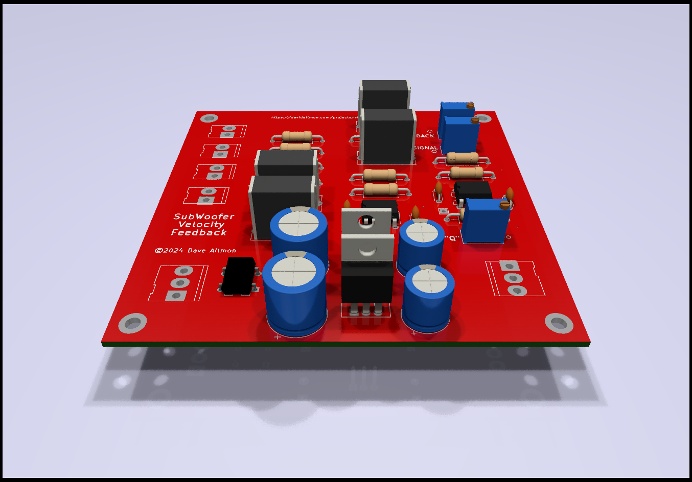
I built the VFB circuit on a 100mm x 100mm PCB. This is a picture of the final board. In my case, it goes in the subwoofer amplifier enclosure, between the inputs and the amplifier, and connects to one voice coil of the driver. You can put it in a separate enclosure with its transformer, or, like me, put it in the amplifier case. See the build page for more on the other parts of the power amps and filters. I decided to make a sub for each channel, and dedicated one channel of a stereo amplifier to each one. It requires two filter boards.
You can make a single-channel sub, by hooking up the low level signal from both channels to the board, and running the output to a mono amp. To run 2, hook the left channel audio signal to the left input on one board, and the right channel to the right input on a second board.
Adjusting the Feedback Circuit
The adjustment procedure needs to be done after the system has been built and otherwise tested. You can set the input level and "SIGNAL" to some small level, and the "FEEDBACK" pot all the way down, and then test the amplifier without the feedback. If you have a dual-channel scope, you can look at the signal and the feedback, and verify that the two are in reasonably correct phase, before cracking open the feedback pot. Correct phase means the feedback peak is sitting between the zero-crossing on the rising edge of the input signal, and the peak on the signal. If it is not in that area, you have to switch the 2 wires of the feedback cable.
There are 3 adjustments that control the behavior of the subwoofer, and a front-panel-mounted pot to adjust the input level. If you don't use the level pot, you need to put a pair of trimmers on the board, or somewhere in the inputs, to adjust the level to match your main speakers. After that, the sub will track the volume of the main speakers without further adjustment. Don't try to control the output voltage - it won't work. Don't try to get the maximum feedback, because the error amp will be dangerously close to oscillation, and the last step would probably throw it over.
The adjustment process starts with all pots, including the external input level pot, at zero (full CCW). Point the sub away from you. A small mistake makes a big noise. The amplifier will be amplifying the oscillation of the feedback circuit at full power. Power everything up and apply a 40Hz signal to the inputs. You shouldn't hear anything from the sub. Adjust the level at pin 3 of U4 using the external level control until it is 50mV using an AC voltmeter on the left or right input terminals on the board.. You still won't hear anything.
Adjust RV4, "SIGNAL", until you have 10mV on pin 5 of U3. As you adjust this, you will start to hear the 40Hz note on the sub. It may get loud. U3B, the error amp, has a gain of 50, so that 10mV becomes 500mV on the input of the power amp, so about half power!
Measure the voltage at TP2. Adjust pot RV1, "FEDBACK IN", until you have 9mV on TP1.
Here's the fun part. Crack open RV3, "FEEDBACK" very slowly. You are listening to the sound of the sub. If it gets a louder, stop, and adjust the pot back to zero. You need to switch the two wires at the "VOICE COIL INPUT" terminals. Open the "FEEDBACK" pot again, slowly. The sound should get quieter. If it does, you're wired right.
Now adjust the "FEEDBACK" pot until the sound gets as quiet as you can get it. If it starts oscillating, back off the "FEEDBACK" pot until it stops.
Adjust the "SIGNAL" pot again, to raise the level back up to where it was.
Repeat the previous 2 steps until any increase on the "FEEDBACK" pot results in the loud oscillation, then back it off a bit to be safe. You now have the ratio of signal to feedback correct, and it is time to adjust the frequency response.
It is down to the "Q" adjustment. It takes the peak in response out. It is all the way CCW, so the filter peaking will be maximum, and the sub sound output at 146Hz will be minimum. The goal is to get the response as flat as possible at around 146Hz. You need a 10Hz to 200Hz sweep signal and a microphone to measure the frequency response of the sub. On the plot, you will probably see a dip in the response at around 146Hz. Adjust the "Q" pot a little and run another sweep. The dip should be either larger or smaller. Keep adjusting and sweeping until the response is as flat as you can get it. It may not be perfectly flat.
As soon as the response is reasonably flat, you're done. You can now use the external level pot to match the sub to your speakers. REW can help with that by running a sweep from something like 10Hz to 400Hz, while adjusting the level control until it matches with the main speakers. You could play with it for days, but the main purpose is to listen to music, so button it all up, put on your best, and listen.
Results
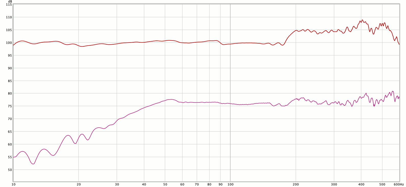
After compensation, the response was flat within ±1.3dB from 10Hz up to 180Hz. YMMV, but I think it turned out good.
Fine Print
Nothing is free. The Dayton SD270A-88 is a nice woofer, but it has a 10" cone. A 10" driver can only move so much air, so it can only get so loud at any given frequency. When you exceed that loudness, the driver gets nonlinear, causing a flat spot on the feedback. The amp will push at full power to try to get the driver to move farther. It makes a very loud click or pop noise as it applies full power to the driver. There is no way around the physics of it. If you need to go lower and/or louder, you need a bigger cone or more of them. That is always true, but with velocity feedback it is more obvious when your woofer gets overextended, since it won't go gracefully nonlinear. The circuit is designed for the SD270A-88, and would need some research to modify for a different driver. The PCB would probably remain the same, but some resistor values will change. Dayton Audio has an SD315A-88 12" DVC subwoofer driver I would like to try, but no 15" version. The 15" dual voice coil drivers all seem to be 2Ω, and I don't currently have an amp that can drive a 2Ω load. The easiest way, I think, is to get something like a cheesy "400W" amplifier board from AliExpress, with 4 pairs of output devices, and run it with a lower voltage, higher current power supply.
Although harmonic distortion is generally improved by a factor of 2 to 3 above resonance, it is still considerable below resonance. Not as much as trying to get 10Hz out of a 43Hz system without feedback, but bad enough. And it takes power to keep the distortion down when operating below resonance. The feedback has to overcome the cone suspension and the air in the box, which favors the resonance of 43Hz, not a 10Hz signal. Still, it really sounds good.
1. Radcliff, Clark J., Gogate, Sachin D. (1996) "Velocity Feedback Compensation of Electromechanical Speakers for Acoustic Applications"