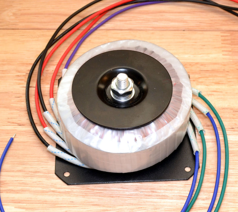
The preamp power supply board requires 2 different voltages. The preamp board uses 2x 22Vac @ 50VA while the mute circuit requires 2x 9Vac @ 25VA. The 22Vac secondaries are in series, giving 44Vct, which makes the ±24V and ±15V supplies. The 9Vac secondaries are in parallel, yielding ~11.5Vdc. That runs the 12V to the input selector and 5Vdc and a 5V pulse to the mute circuit.
The toroidal transformers are magnetically pretty quiet, but to make sure, I added steel covers to both transformers. They have the added benefit of holding the bolt in the bottom up away from the bottom of the case, so I didn't have to drill a hole in the case and run the center bolt through it. The can sizes for the 2 transformers are 90mm x 50mm and 105mm x 50mm.
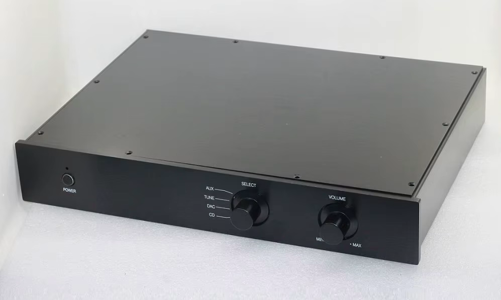
The enclosure I picked was the same type I used for rev 3. It has a divider from front panel to rear panel which splits the enclosure into a left side and a right side. The left side has the power IEC input connector, transformers and power switch. It uses about 1/3 of the total space. The right side is the other 2/3 of the space and contains the input and output jacks, the selector switch, the stepped attenuator and the input relay board. This is where the preamp and power supply PC boards go.
The output RCA jacks are CMC knock-offs. They're high quality, but CMC didn't make them.
You'll see in other pictures the knobs are different. I replaced the smooth ones with knurled knobs. The smooth ones didn't work well with the rotary switch.
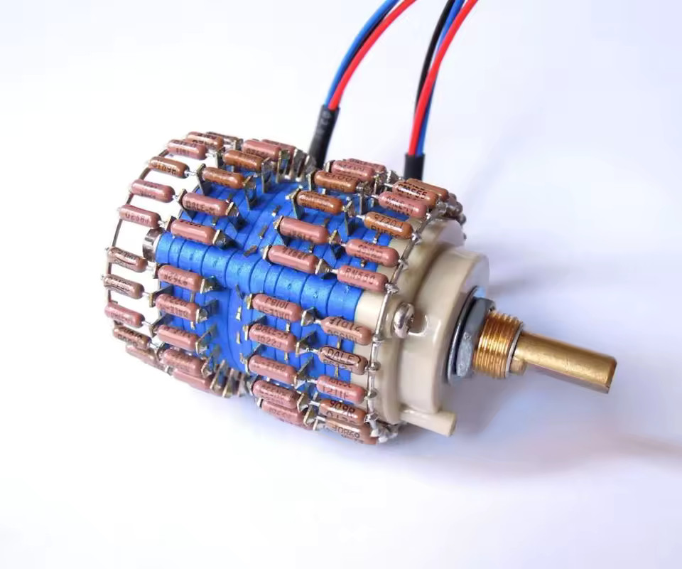
This is the stepped attenuator I’m using for the volume control. AliExpress carries a number of types, using Dale “brown” resistors, standard 1% resistors, or chip resistors. There are chip resistor versions from $16.95 to $97.00. I doubt there is any advantage to paying more for a more-or-less identical unit. I would recommend staying away form the open-frame style switches. They don’t have the uniformity to feel consistent throughout the range. The blue stacked ones are more well aligned, and feel consistent. And cost more.
Rev 3 had an Allo 10kΩ stepped attenuator, but I can't find them anywhere. Their website says they will be back in business soon. It has said that for several years.
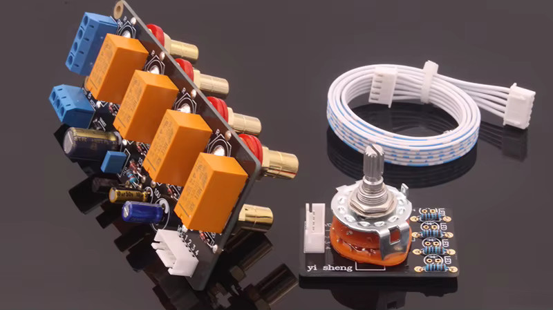
The input selector is also the same as I used on rev3, having the audio on the board and the rotary switch on the front panel. Only the Vcc goes to the front panel – no audio signals. The board has separate grounds for the two channels and a separate power ground. The RCA jacks are gold-plated brass. There are LEDs that can mount on the front panel board, but I didn’t use them because I’m not dilling 4 holes in that beautiful front panel.
The rotary switch is kind of rough to start with, but smoothes out after a few weeks of playing with it. I’m not fond of open-frame rotary switches because they are so inconsistent mechanically.

The power wiring is divided into 3 types: AC Mains, AC Low voltage, and DC. I tried to keep them as separate as I could.
The signal wiring is straightforward - the preamp main board is configured in such a way that the wiring is in a more-or-less ideal place.