A DIY HiFi Audio Preamp
Page 1 Page 2 Page 3
Revision 5.4 improves upon rev 3 with four main upgrades: a DC servo using an OPA227PA op amp (as opposed to a DC-blocking capacitor) to eliminate output offset, an upgraded C0G feedback capacitor, a new buffer stage with a 990C+ op amp that lowers output impedance and adds another 6dB of gain, and a 4-layer PCB, so I could get more effective ground plane area.
The DC servo passes only low-frequency content (DC to ~1Hz), removing unwanted offset at the volume control and power amp input. The OPA227PA's typical ±5μV input offset results in a manageable 150μV power amp output, far better than trimmer pots could achieve—I abandoned a previous trimpot-based offset adjustment (rev 4) after realizing I couldn't measure microvolts accurately. The offset adjustment now takes place on the OPA227PA, but is measured at the output of the discrete op amp.
The preamp centers on the John Hardy 990C+ discrete op amp, which delivers exceptional performance: 0.005% distortion at +21.8dBV (12.3Vrms) output, at 20kHz, into a 75Ω load. That is running class AB. As long as the output load is ≥1500Ω, it runs class A. While more affordable op amps exist, the 990C+ offers a level of performance that makes it difficult to settle for anything else once you've heard it. Discrete op amps dramatically outperform monolithic alternatives, due in large part to their thoughtful design and quality manufacturing. One advantage is that the designer can use the part that is most suitable for a particular purpose, rather than settling for the best compromise in a monolithic device.
The preamp design is straightforward: power switch, input selector, volume control. Discrete op amp cost is anywhere from ~$70 to $200, depending on the configuration and discrete you choose. You could simplify to two op amps by running the volume control directly to the outputs—rev 3 did this after I discovered the monolithic buffer stage (OPA2134PA) degraded the sound quality, leaving it skinny and lifeless. The change brought it back to life, but to be complete the preamp needs to buffer the volume control to isolate the power amplifier from the high and variable source impedance caused by the volume pot. If you decide to go the 2-op amp route, use a 10kΩ potentiometer for the volume control.
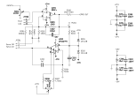
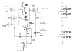
You can see from the schematics that the two amplifier sections are nearly identical. The 990's have a gain of 2, for two reasons: 1) Although they are unity-gain-stable the manufacturer recommends at least +6dB gain. 2) The DC servo needs a feedback circuit to work in a non-inverting mode.
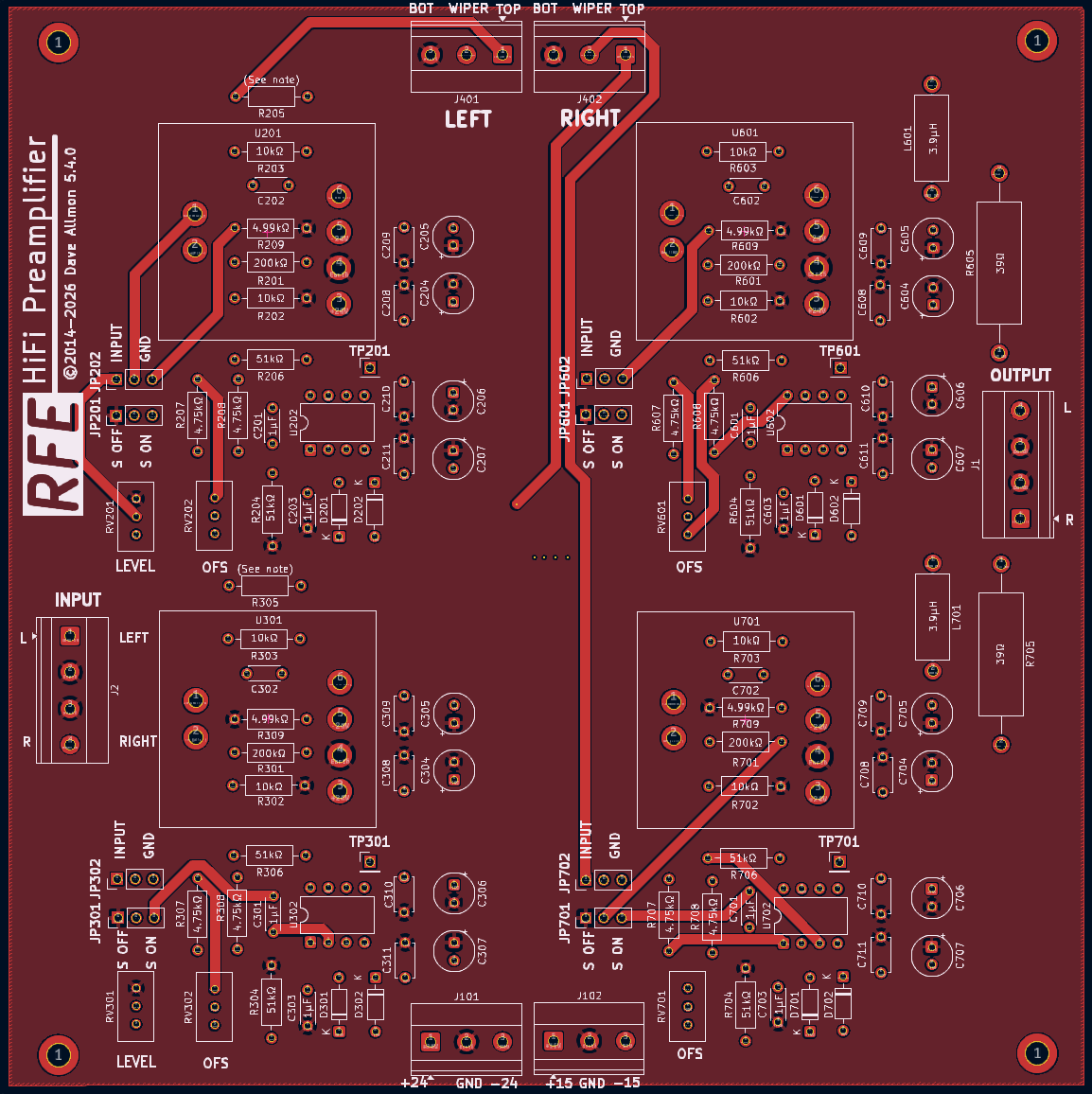
There is an output isolation circuit on the buffer stage, R605/L601, to keep the stage from acting up when it sees a long cable. L601 is a small, 39μH inductor in parallel with R605, a 39Ω resistor. The same goes for R705/L701. At lower frequencies the coil has minimal impedance and the resistor is bypassed. At higher frequencies the coil's impedance becomes larger, and the total impedance becomes the parallel resistance of R605 and L601, which appears in series with the capacitance of the cable.
Notes:
R205 - R305: Use this resistor if the preamp's output is too hot, leaving too little usable range on the volume control. Size it so with the volume control and the two level trim pots at full open, the maximum output sits just above your target level at the outputs of the buffer stages. A resistor of the same value as the volume pot will cut the output in half. The default is a 0Ω resistor. Then adjust the level down to where you want it using RV201 and RV301. See "DC Offset Adjustment" and "Level Calibration" on page 3.
PC Boards
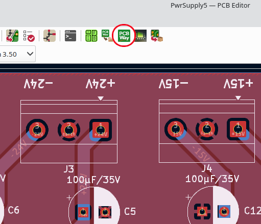
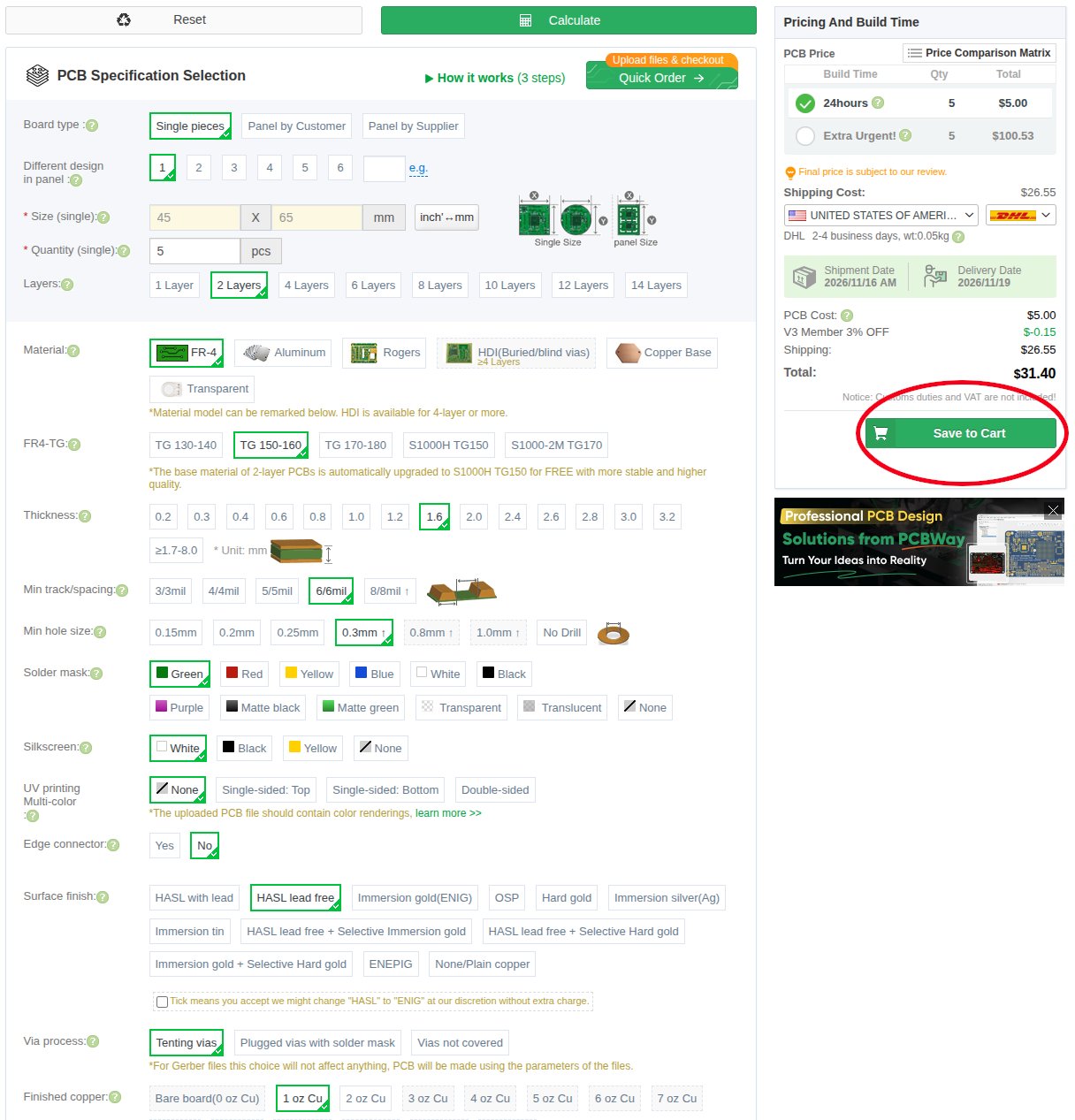
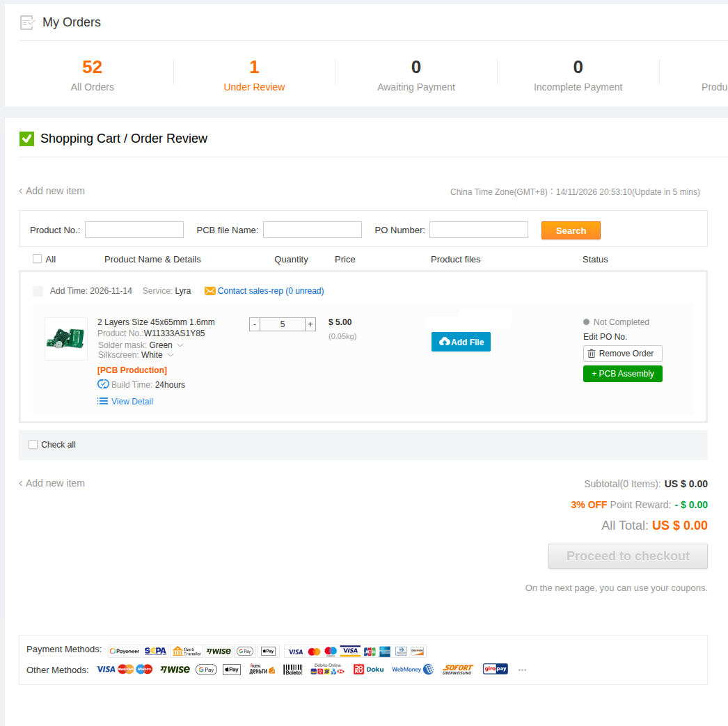
I designed the PCB first as a 2-layer board, but was unhappy with the sprawl of the components. To get the ground plane coverage I wanted, separation of the power supply lines from the signals, and to keep the traces short I needed a 4-layer board. The design was straightforward, with the help of KiCad v9. So was ordering the boards. KiCad has a plugin module named "PCBWay", which makes the whole ordering process easy. When I'm satisfied with a design, I load the browser and login to PCBWay.com, then I push the "PCBWay" button on the KiCad top toolbar. In about 3 seconds it opens a tab in the browser with a filled out request for online quote. All I do is pick the solder mask color, the surface finish (HASL) and enter the quantity, which defaults to "5". I generally get 5 or 10 boards, depending on whether I am prototyping or not, and on my confidence with the design. Then I click the big green "Calculate" button on the upper right, make sure everything looks good, and if not change it, and click "Calculate" again. If I am satisfied that everything is correct, I click on the "Add to Cart" button. That takes me to the cart page, where I see that the order is under review. When PCBWay has finished reviewing my board, the page will change to "Awaiting Payment". I pay for it, and production begins soon after. I can monitor progress on the Production Status page, by clicking on the "Production Tracking" button associated with my board.
Refer to the screen captures below.

In a few days your package arrives, and you open it...
And you have some very well-made PC Boards from PCBWay...
Power Supply
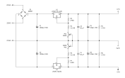
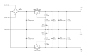
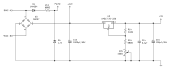
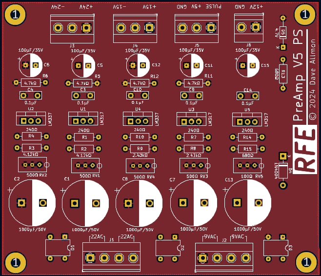
The topology of the ±24V and ±15V supplies is identical. The only difference is the value of 2 resistors. 4.12kΩ on the ±24V supply and 2.43kΩ on the ±15V supply. The values are marked on the board. If you have chosen a ±18V discrete op amp, you would change the value of those 2 resistors on the ±24V supply from 4.12kΩ to 2.94kΩ, and adjust the outputs to 18V.
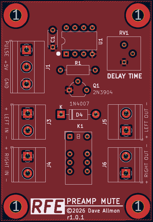
The ±24V supply may be adjusted from 22.7V to 25.3V. The ±15V supply may be adjusted from 13.9V to 16.5V. The 5V supply may be adjusted from 4.8V to 5.3V. The pulse is fixed. It is a 60Hz sort-of square wave signal. That and the 5V supply are used by the mute board. The unregulated 12V power goes to the relay input selector on the back panel. The 5V and 12V ground is isolated from the preamp ground.
Mute Board
PCBWay.com provided all PC boards used in this project.